


Basics of Equalization 3
Multiple Band Edit
Selecting an Edit Group
Pressing a [BAND SELECT] button puts the DEQ830 into Edit
mode. And until you turn the [VALUE] encoder to boost or cut
the gain, you can keep pressing [BAND SELECT] buttons until
you have several of them selected simultaneously. This is called
selecting an Edit Group. An Edit Group can be made up of any
number of bands. Another way to select an edit group is to hold
down a [BAND SELECT] button and turn the encoder. This
will allow you to select a range of bands at once.
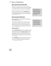
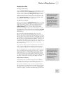
There’s an easy way to create
an Edit Group from multiple
adjacent bands. Just press
and hold a [BAND
SELECT] button as you spin
the [VALUE] encoder left or
right. The farther you spin the
encoder, the more bands you
will select. After you release
the [BAND SELECT] button,
y
ou can use the encoder to
adjust the gain of all selected
bands at once.
The Relative Gain display
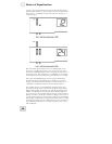
When you pressed the first [BAND SELECT] button, two things
happened: the Numerical LED Display changed to show the gain
value of that band, and one of the corresponding Band Gain
LEDs started to blink. Then, when you pressed the second
[BAND SELECT] button, two more things happened: the
Numerical LED Display changed to show the number “0,” and a
second Band Gain LED started to blink. Each additional [BAND
SELECT] button you press adds a band and a blinking LED to
the Edit Group.
But why did the Numerical LED Display change to a zero?
Because, once you have selected an Edit Group, you can cut or
boost the gain of all of the bands in the Edit Group at once. They
will move up or down together. The zero in the display represents
a “benchmark” for the amount of gain change that happens to the
Edit Group. The 7-segment LEDs can't display the gain values of
each band within the Edit Group all at once, so if you raise the
overall level of the Edit Group by 2 dB, that’s the number you will
see. The function of the display in this case is to tell you the
Relative Gain amount.
For the sake of clarity, when this manual describes what is shown
in the 7-segment LEDs while changing the overall gain value of
the Edit Group, we will refer to it as the Relative Gain display.
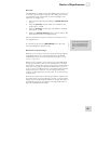
For maximum preservation of
f
idelity of the input signal, the
largest number of bands in a
channel should be set to 0 dB.
For example, if you have
more than half of your bands
set to some cut amount and
the majority of those cut
f
requencies are at -4 dB, then
select all bands and
compensate by +4 dB.
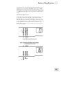
Here’s an example: let’s say you have selected the bands at 4k and
5k as your Edit Group. The initial gain value for 4k is +2 dB and
the gain value for 5k is -2 dB. The Relative Gain display at this
point will read “0.” If you rotate the encoder clockwise through
four values, the final value of the Relative Gain display will be a
“2.” The actual gain values for 4k and 5k are now +4 dB and 0 dB,
respectively, which will be indicated by their Band Gain LEDs.
Proportional Gain Memory
It’s possible you may see numbers as large as 24 in the Relative
Gain display. This is due to a very powerful aspect of the Relative
Gain feature, and it will require some careful explanation.
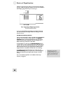
Here’s another example. Let's say you have two bands selected.
The first band is set to 0 dB, and the second band is set to -12 dB.
The Relative Gain display reads “0.” If you turn the [VALUE]
encoder to the right, you will see that number change from 0 to 12
37