


22
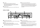
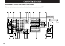
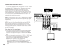
REAR PANEL SWITCH AND CONTROL
SETTINGS
There are several switches and controls on the rear panel that
you’ll have to check before operating your system, and it’s a good
idea to do it before you connect cables. First, locate the MAIN
LEVEL slide switch (F). Make sure the MAIN LEVEL switch is set
to “0 dB”.
For General model only, set the NTSC/PAL switch (E) to the
position corresponding to the standard which your video
equipment employs and set the FREQUENCY STEP switch (2) to
the position suitable for the frequency spacing in your area.
For the setting of IMPEDANCE SELECTOR switch (0), see
page 34.
For the setting of the center speaker switch (9), see page 32.
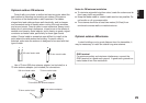
GENERAL INSTRUCTIONS FOR
CONNECTIONS
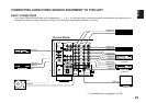
Make sure that you have the left (L) and right (R) channels
correctly connected. That means that jacks marked “L” on this unit
must be connected to jacks marked “L” on other units. Likewise
with the “R” jacks. This is easy if you remember to always use the
red plug for the “R” jacks and the white plug for the “L” jacks.
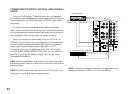
For connections with audio/video source equipment, use RCA
type pin plug cables with the exception described later.
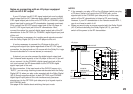
With speaker connections you must also be sure that the
polarity is correct. For each amplifier and each channel, connect
the plus (+) terminal of the amplifier to the plus terminal of the
speaker, and connect the minus (–) terminal of the amplifier to the
minus terminal of the speaker. To keep track of polarity, use a
speaker cable that has one of the two wires marked by a stripe or
a different color.