


19
English
INTRODUCTION
PREPARATION
BASIC OPERA-
TION
ADVANCED
OPERATION
ADDITIONAL
INFORMATION
APPENDIX
CONNECTIONS
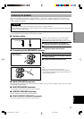
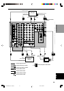
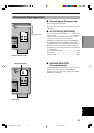
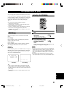
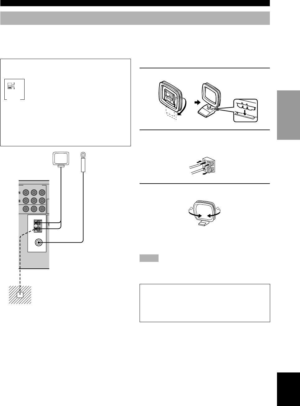
■ Connecting the AM loop antenna
1 Set up the AM loop antenna, then connect it.
2 Press and hold the tab to insert the AM loop
antenna lead wires into the AM ANT and
GND terminals.
3 Orient the AM loop antenna for the beat
reception.
y
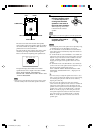
• The AM loop antenna can be removed from the stand and
attached to a wall, etc.
Notes
• The AM loop antenna should be placed away from this unit.
• The AM loop antenna should always be connected, even if an
outdoor AM antenna is connected to this unit.
A properly installed outdoor antenna provides clearer
reception than an indoor one. If you experience poor
reception quality, an outdoor antenna may improve the
quality. Consult the nearest authorized YAMAHA
dealer or service center about the outdoor antennas.
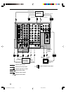
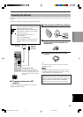
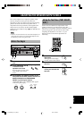
Connecting the Antennas
Both AM and FM indoor antennas are included with this unit. In general, these antennas should provide sufficient signal
strength.
Connect each antenna correctly to the designated terminals.
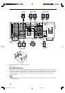
■ Connecting the indoor FM
antenna
Connect the included indoor FM antenna to the 75Ω
UNBAL. FM ANT terminal.
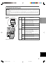
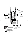
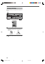
FREQUENCY STEP switch (For China model)
Because the interstation frequency spacing
differs in different areas, set the
FREQUENCY STEP switch (locating on
the rear panel) according to the frequency
spacing in your area.
North, Central and South America:
100 kHz/10 kHz
Other area: 50 kHz/9 kHz
Before setting this switch, disconnect the
AC power plug of this unit from the AC
outlet.
Ground (GND terminal)
For maximum safety and minimum
interference, connect the antenna GND
terminal to a good earth ground. A good
earth ground is a metal stake driven into
moist earth.
Indoor FM
antenna
(included)
AM loop antenna
(included)
TUNER
75Ω
UNBAL.
AM
ANT
GND
FM ANT
COMPONENT VIDEO
P
R
/ C
R
V
D
N
ITOR
U
T
BL
AT
P
B
/ C
B
Y
100kHz/10kHz
FREQUENCY
STEP
50kHz/9kHz
FM AM
0103HTR5590_10-20_EN(U) 02.8.5, 4:29 PM19