


12
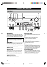
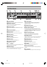
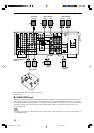
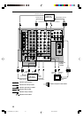
SPEAKER SETUP
AC OUTLETS
CENTER
SUB
WOOFER
S VIDEO
MONITOR OUT
VIDEO
DIGITAL OUTPUT
DIGITAL
INPUT
6CH INPUT
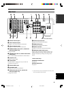
GND
AUDIO AUDIO VIDEO
CONTROL
OUT
SPEAKERS
TUNER
REMOTE
IN
75Ω
UNBAL.
OUT
AM
ANT
GND
FM ANT
+12V
15mA
MAX.
COMPONENT VIDEO
S VIDEO
DVD
D-TV
/LD
CBL
/SAT
VIDEO
P
R
/ C
R
DVD
MONITOR
OUT
CBL
/SAT
MAIN
REAR
REAR
CENTER CENTER
OUTPUT
IMPEDANCE SELECTOR
SET BEFORE POWER ON
SUB
WOOFER
P
B
/ C
B
Y
R
R
L
L
R
L
R
L
OPTICAL
MD
/
TAPE
IN
(
PLAY
)
IN
(
PLAY
)
OUT
(
REC
)
OUT
(
REC
)
CD-R
CD-R
MD/TAPE
CD-R
DVD
CBL
/SAT
CD
CD
PHONO
IN
OUT
OUT
ZONE 2 OUT
VCR 2
/DVR
VCR 1
IN
MAIN
SURROUND
CD
D-TV
/LD
(SURROUND)
COAXIAL
+
–
+
–
+
–
+
+
+
+
+
–
–
–
–
–
MAIN A OR B:
A+B:
CENTER
4ΩMIN. /SPEAKER
8ΩMIN. /SPEAKER
6ΩMIN. /SPEAKER
6ΩMIN. /SPEAKER
6ΩMIN. /SPEAKER
8ΩMIN. /SPEAKER
8ΩMIN. /SPEAKER
8ΩMIN. /SPEAKER
8ΩMIN. /SPEAKER
REAR
REAR CENTER
:
:
:
MAIN A OR B:
CENTER
REAR
REAR CENTER
:
:
:
A
B
2
6745
31
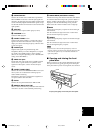
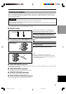
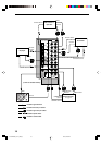
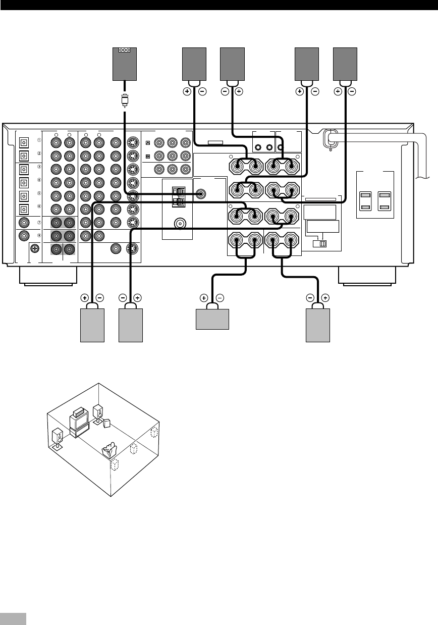
Subwoofer
system
Rear Center
speaker
Main B speaker
Center
speaker
(U.S.A. and Canada
models)
Right
Rear speaker
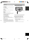
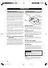
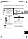
■ SUBWOOFER jack
When using a subwoofer with built-in amplifier, including the YAMAHA Active Servo Processing Subwoofer System,
connect the input jack of the subwoofer system to this jack. Low bass signals distributed from the main, center and/or
rear channels are directed to this jack if they are assigned to this jack. (The cut-off frequency of this jack is 90 Hz.) The
LFE (low-frequency effect) signals generated when Dolby Digital or DTS is decoded are also directed if they are
assigned to this jack.
Note
• Depending on the settings of “1 SPEAKER SET” and “10 LFE LEVEL” on the SET MENU, some signals may not be output from
the SUBWOOFER jack.
Right Left
Main A speaker
Right Left
Left
2
3
1
6
7
5
4
The diagram above shows the speaker layout in the
listening room.
0103HTR5590_10-20_EN(U) 02.8.5, 4:29 PM12