


Page: 74 Model MRC88m / MRAUDIO8x8m
© 2009 Xantech Corporation
Connecting two units via their Expansion port, provides for seamless 8 Source / Sixteen Zone operation,
allowing the same Zone Linking, Priority Lockout, and Monitor Lockout features throughout all SIXTEEN zones.
IR Routing is also supported in this mode.
NOTE: During the EXPANDED Set-Up instructions, we will refer to the PRIMARY and SECONDARY
Controllers. The PRIMARY Controller refers to the MRC88m Controller connected to Zones 1 thru 8 and
the SECONDARY Controller refers to the MRC88m Controller connect to Zones 9 thru 16.
PROGRAMMING IN EXPANDED MODE
An EXPANDED system is programmed much the same way as a non-Expanded system. All programming
aspects for EXPANDED mode has been discussed in detail throughout the manual in the appropriate sections
subtitled (ADVANCED/EXPANDED). The key areas are listed here for reference. If more explanation is
needed, please see the corresponding complete section in the manual.
E
NABLING EXPANDED MODE
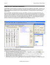
1. With a project OPEN in the Dragon Drop-IR™ Software, make sure the USER SETTINGS Menu is set
to ADVANCED mode of operation (If not, select ADVANCED DRAGON in the User Settings menu).
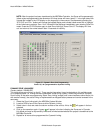
2. Select the CONTROLLER tab in the MRC88m Systems Window.
3. In the EXPANDED OPTIONS section of the CONTROLLER window, select EXPANDED
NOTE: If any programming has already been completed prior to selecting EXPANDED, all programming will
still be preserved in Zones 1-8. You may now proceed to complete programming for all 16 Zones.
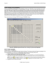
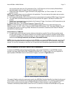
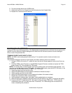
4. Select the ZONES tab in the MRC88m Systems window. In the SELECT ZONES section, you should
notice buttons for ALL sixteen zones. Press any of these buttons to program the Zones Virtual Keypad.
P
ROGRAMMING THE SYSTEM
Refer to Section 4 and follow all instructions for EXPANDED mode.
1. Place commands from Palettes under any button on the virtual keypad as outlined in Section 4.
NOTE: If commands have already been placed on any of the Keypads in Zones 1 thru 8 and PUNCHED for
all zones (system level) prior to enabling EXPANDED mode, those buttons will need to PUNCHED again if
needed in Zones 9-16.
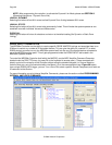
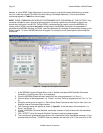
2. When EDITING COMMANDS in the Macro Command List, you will now be able to select Zones 1 thru
16 in the IR IN ZONE sub-menu. (Right-Click on individual commands in the Macro Command List to
access the sub-menu).
3. Test commands in the same manner as noted above.
4. Continue through Section 5 for setting Zone Linking, Monitor Lockout and other desired features.
IMPORTANT NOTE: Internal Amplifier Commands cannot be communicated from Controller to Controller.
These commands can be used for zones running through a single Controller.
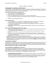
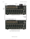
PHYSICAL CONNECTIONS IN EXPANDED MODE
In EXPANDED mode, some connections are made to the PRIMARY and SECONDARY Controllers and others
are ONLY made to the PRIMARY Controller. A guide line for specific connections is listed below. Please refer
to Figure 42.
1. Connect all Source Components to the PRIMARY Controller [Figure 3-(22)].
2. Connect the A/V Loop-Through Connectors on the rear of the PRIMARY MRC88m Controller [Figure 3-
(23)] to the corresponding Source AV Inputs on the rear of the SECONDARY MRC88m Controller
[Figure 3-(22)]
3. Connect the Source Emitter Outputs on the PRIMARY Controller [Figure 3-(26)] to the Source
Components IR Sensor Windows.
4. Using the supplied DB15 MALE/MALE cable, plug one end into the EXPANSION Port on the rear of the
PRIMARY Controller [Figure 3-(30)] and the other end to the EXPANSION Port on the rear of the
SECONDARY Controller [Figure 3-(30)].