


Model MRC88m / MRAUDIO8x8m Page: 31
© 2009 Xantech Corporation
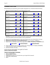
Note: The 12VDC output terminal is rated at 100mA and can power up to one
SMARTPAD/WATERPAD Keypad or up to 4 IR Receivers. Anymore then this will require the use of an
external power supply. Do not wire the external power supply to the MRC88m keypad. Wire
directly to the units to be powered.
The STATUS line is an output and is active Hi (+12VDC) when the MRC88m Keypad is powered ON
and is LOW (0VDC) when the Keypad is OFF. Use this to provide Bank Tracking LED on the
SMARTPAD/WATERPAD keypad or other.
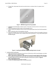
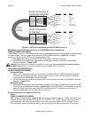
In Zone IR
To wire local emitters in-the-zone (emitters used to control components in the same general area as the
keypad), wire the IR OUT and GND terminals on the rear of the MRC88m Keypad –Figure 5-(22) to the
IR (white stripe) and GND of the emitter cable. To control numerous components in the same area, wire
these terminals to an amplified connecting block (Xantech 791-44) using 18-20AWG 2-conductor cable.
A 2-conductor screw-type removable connector is provided.
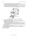
ZONE EXPANSION (CONNECTING TWO MRC88M CONTROLLERS)
(EXPANDED)
For systems greater than 8 Zones, two MRC88m Controller/Amplifiers can be linked together for systems up to
16 Zones. Zone expansion is only available in Advanced programming configurations.
L
INKING TWO MRC88M CONTROLLER/AMPLIFIER UNITS
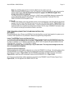
To connect two systems, simply connect the supplied DB15 Expansion Cable to the EXPANSION Port on the
rear of one unit to the EXPANSION Port on the other – Figure 3-(30). These units should be placed either side
by side or if installed in a 19” (483mm) equipment rack, leave 2 rack unit spaces (2U space) between the two
units [One Rack Unit space = 1-3/4” (44.5mm) in height].
CAUTION: Do not place these units directly on top of each other. This may cause damage to the units
due to increased heat dissipation.
C
ONNECTING SOURCE COMPONENTS
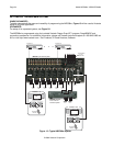
When connecting two units together, designate one unit as the PRIMARY Unit (Zones 1-8) and the other unit as
the SECONDARY Unit (Zones 9-16). All source components should be connected directly to the PRIMARY
Units Source A/V Inputs – Figure 3-(22). Use the PRIMARY Units Audio and Video Loop-Thru connectors –
Figure 3-(23) to feed the source component inputs of the SECONDARY Unit – Figure 3-(22).
All of the source components emitters should be connected to the PRIMARY Units IR Emitter Output Ports –
Figure 3-(26). This rule applies to the SENSE INPUTS also.