


Model MRC88m / MRAUDIO8x8m Page: 21
© 2009 Xantech Corporation
b) Press “VOL+” on the Zone 1 Keypad. The Volume bar should move on the Keypad and the audio
content of the source connected to the Source 1 inputs should be should be heard through the Zone 1
speakers.
c) Press “MUTE” on the Zone 1 Keypad. The Zone 1 speakers will mute. Press MUTE again and the
speakers will un-mute. (Pressing VOL+ or VOL- will also un-mute the speakers).
d) Use the source 1 original equipment remote and verify that all source functions operate when aiming
the remote at the Zone 1 Keypad IR sensor.
e) Press “POWER” on the Zone 1 Keypad and verify ALL Status LED’s on the Controller Front Panel are
OFF.
8. Move the Audio/Video Source component to SOURCE 2 Audio Left/Right and Video Input terminals;
Speakers to Speaker Output #2 and the TV/Video Monitor to Video Out #2.
9. Repeat Steps 5 thru 8 for source/Zone 2 thru 8
Note: For Zones 7 & 8 Speakers will be connected to the Speaker A and B output of the PA435x
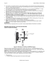
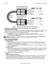
Caution: Power voltage for the keypad is transmitted along the CAT5 cable! Incorrect wiring on this cable
can destroy the MRC Keypad. Please test the cable connections using a proper CAT5 cable tester
or using a Multimeter to check Pin to Pin continuity and for possible shorts. Using either method, it is
advisable to measure pins 3 and 6 to verify proper voltage with a Multimeter. A 12Vdc measurement
should be read when the positive probe is on pin 6 and the negative probe is on pin 3. See Figure
10.
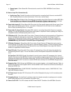
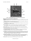
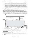
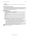
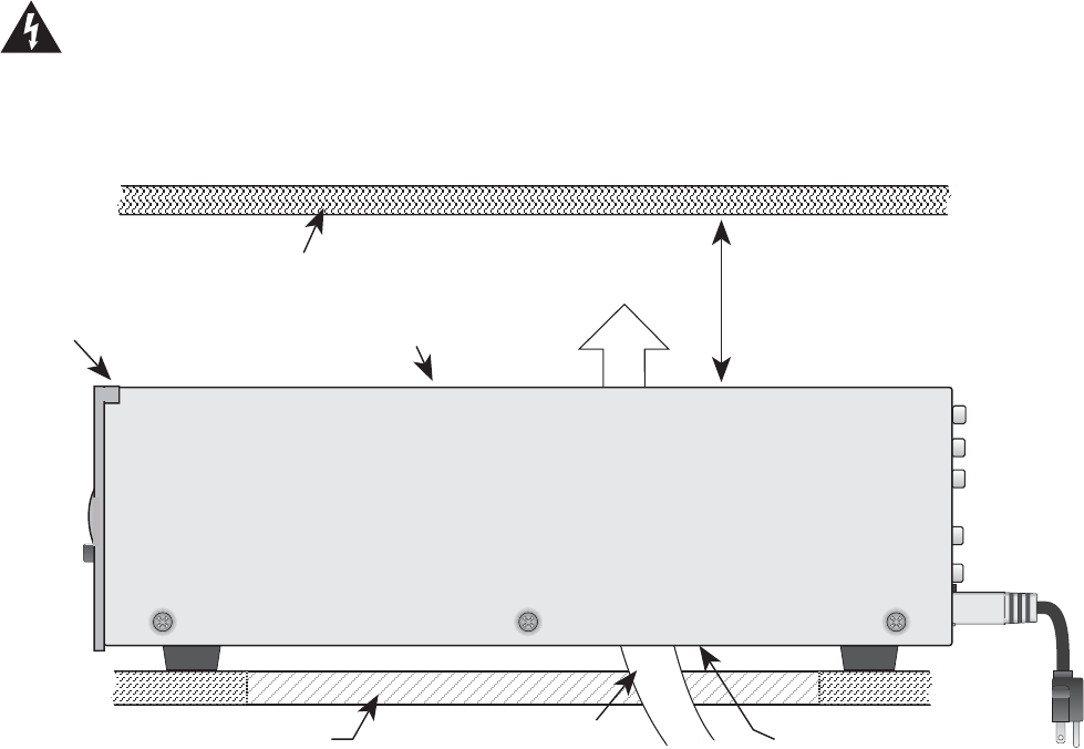
Upper shelf, component, wall, etc.
2-inch spacing
(minimum)
MRC88
To maximize air flow, route
single large opening in lower shelf.
Keep perforations on top cover free
of obstructions!
Keep perforations on bottom
plate free of obstructions.
Convection
Airflow
Figure 6A: MRC88m CTLR mounting
MRC88M CONTROLLER/AMPLIFIER PHYSICAL LOCATION AND MOUNTING
(BASIC/ADVANCED)
When you mount the MRC88m Controller, you should plan its location carefully. Pay close attention to each of
the following factors (refer to Figure 6A above):
1. The amplifier is convection cooled. That is, it depends on the natural free flow of air up through the slot
perforations in the bottom plate, over the internal heat dissipating fins, then out the top cover, for adequate
cooling.