


Model MRC88m / MRAUDIO8x8m Page: 15
© 2009 Xantech Corporation
29
30
31
2426
27
20
23
22
25
19
28
17
18 16
34
21
33
32
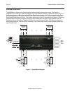
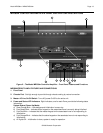
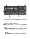
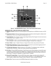
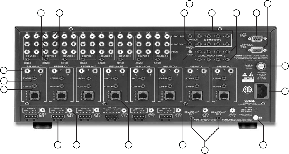
Figure 3 – The Model MRC88m Controller/Amplifier – Rear Panel Connections and Functions
MRC88M REAR PANEL FEATURES AND CONNECTIONS:
16. Keypad Terminals (8). Each Zone has one RJ-45 jack for Keypad Interface. Each connector interfaces the
following: Power (Enough for 1 Primary & up to 4 Secondary Keypads per Zone), RS-485 Data I/O, and IR
Input.
17. Speaker Terminals (6). Plug-in 4-terminal screw type connectors for zones 1 thru 6, permit speaker wire
sizes up to 12AWG.
18. Composite Video Output (8). RCA type connector sends zone selected, source video to the composite
video input on a zone TV or modulator (Applies to MRC88m only).
19. Status Out (8). Provides a control output of +12 VDC that turns on and off with the zone to drive voltage
sensing relay modules and AC strips.
20. Control Out (8). Mono 3.5mm Mini Phone Jack provides a Control Output that goes high (+12 volts) when
any Zone is first turned ON and goes low (0 volts) when the last Zone is turned OFF. [Tip=+VDC;
Shield=GND]
21. Remote Amp Control Out (CO1 & CO2). Stereo 3.5mm Mini Phone Jack connects to CONTROL IN
jack of Remote Amp PA435X or PA4100X. Provides STANDBY and MUTE Control of remote Amp from
Zone 7 (CO1) and Zone 8 (CO2). [Tip = STANDBY Logic; Ring = MUTE Logic; Shield = GND]
22. Source Component Input Connections (8)
a) Source Audio Inputs. Gold-plated RCA Jacks for Stereo/Dolby Pro line level audio input from source
components.
b) Source Video Inputs. Gold-plated RCA Jacks for composite video input from source components
(Applies to MRC88m only).