


Page: 46 Model MRC88m / MRAUDIO8x8m
© 2009 Xantech Corporation
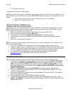
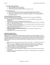
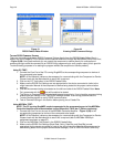
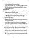
Figure 21
RS232 Palette Editor Window
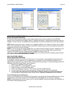
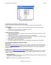
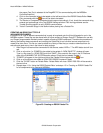
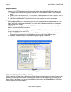
Figure 22
Entering RS232 Command Strings
TESTING RS232 COMMAND STRINGS
There are two methods of testing RS232 Command Strings directly from the RS232 Palette Editor: One is
directly out of the DragMRC PC’s Comport and the second method is through the MRC88m’s RS232 Com Port
– Figure 3-(29). Using both methods you can control the component or device directly for confirmation of
command string or send the command to an RS232 Utility programming to verify proper output (this is good for
Trouble Shooting purposes or for testing the program without the component or device present).
Using PC TEST:
1. Connect the Com Port of the PC running DragMRC to the corresponding component or device of
the commands to be tested.
NOTE: A “Null Modem” cable may be necessary for communicating with the Component or Device.
Please check with the Manufacturer to see if this is required.
2. Click on the ‘PC Test’ button in the RS232 Palette Editor.
3. Make sure the RS232 Port Settings are set appropriate for the device connected to (refer to the
mfg’s Instruction Manual of the component or device being tested for the proper communication
settings)
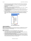
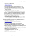
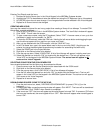
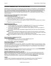
4. Click on the command string to be tested on the left-hand side of the RS232 Palette Editor. Note:
Only commands with the
icon will be able to be tested.
5. The Device or Component connected should respond accordingly. If not, check the command string
entered and port settings in the Test RS232 Settings window. If still having problems see the
Trouble Shooting section to verify RS232 communication.
6. Test all Command Stings in this fashion before placing into a Palette File.
Using MRC88m TEST:
NOTE: The PC running DragMRC needs to connected to the programming port of the MRC88m
Controller/Amplifier and communication verified (Base Unit “Who Am I”) before continuing.
1. Connect the Com Port on the rear of the MRC88m Controller/Amplifier – Figure 3-(29) to the
corresponding component or device of the commands to be tested.
NOTE: A “Null Modem” cable may be necessary for communicating with the Component or Device.
Please check with the Manufacturer to see if this is required (refer to MRC88m RS232 pin
assignment as shown on page 97).
2. Click on the ‘MRC88m Test’ button in the RS232 Palette Editor.
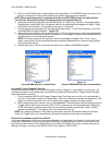
3. Make sure the RS232 Port Settings (Baud Rate, Parity, Data Bits, and Stop Bits) are set
appropriate for the device connected to (refer to the mfg’s Instruction Manual of the component or
device being tested for the proper communication settings). Click on PREFERENCES and verify