


Page: 16 Model BXAUDIO4X4
© 2005 Xantech Corporation
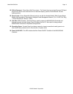
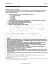
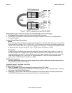
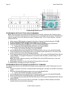
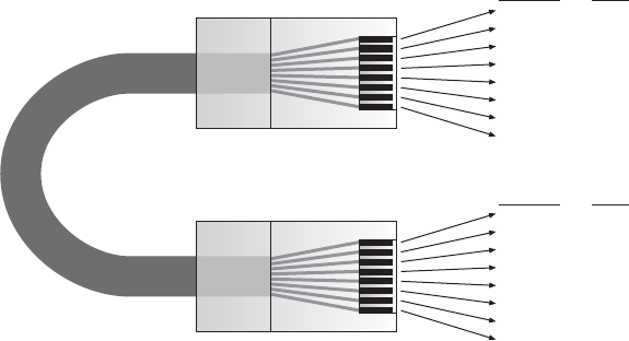
Wire Color Signal
white/orange Tx+
orange Tx-
white/green 12V RET
blue IR RET
white/blue IR
green +12V
white/brown Rx+
brown Rx-
Cat 5
Cable
RJ45 Connector at
Controller/Amplifier
RJ45 Connector
at Keypad
Wire Color Signal
white/orange Rx+
orange Rx-
white/green 12V RET
blue IR RET
white/blue IR
green +12V
white/brown Tx+
brown Tx-
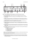
Figure 7 - CAT5 Pin Assignments (per EIA/TIA 568B)
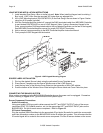
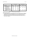
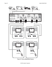
BXAUDIO4X4 Keypad Cable Connections at the BXAUDIO4X4 Controller/Amplifier
1. See Figure 6 for termination of the CAT5 cables to the RJ45 connectors.
2. Connect the zone keypad to the appropriate zone Keypad connector on the rear of the BXAUDIO4X4
Controller/Amplifier.
Control Out and Status Connections
Status
Each zone has a Status Output that provides a control output of +12 VDC, 50mA that turns on and off with
the zone ON/OFF condition. ON = +12VDC, OFF = 0VDC. Using a 3.5mm mono mini phone connector, this
control can be used to close a relay, such as a Xantech CC12, to raise a TV lift or drop a projection screen
automatically when a zone is turned ON. (Tip = 12VDC Control Out, Sleeve =- GND)
Control Out
A single Common Control Output is provided. When the Common Control Output is High (+12 volts, 50
mA), this indicates that at least one zone is ON. When the Common Control Output is Low (0 volts), this
indicates that all zones are OFF. Using a 3.5mm mono mini phone connector, this control can be used to
close relays (Xantech CC12) or turn on an AC outlet (Xantech AC1, AC2) for activity common to the
system. (Tip = 12VDC Control Out, Sleeve =- GND)
AC Power Connections
Use the supplied power cable and plug into a power source capable of delivering the rated amps shown in
the specification section of this manual.
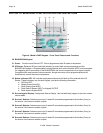
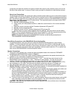
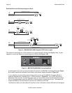
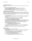
CONNECTIONS AT THE ZONE LOCATION
Single Keypad Connections
1. Refer to Figure 10 for proper termination at the zone-end of the CAT5 cable.
2. Connect the CAT5 cable from the BXAUDIO4X4 Controller/Amplifier into the RJ45 jack marked “Controller”
on the rear of the BXAUDIO4X4 keypad.
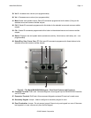
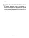
3. Depending on the number of BXAUDIO4X4 keypads and IR receivers used in a zone the jumper pins on
the BXAUDIO4X4 keypad are to be connected as shown in the following table: