


LC Filter
4-10
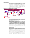
4.5 LC Filter
The LC filter serves two purposes in this design.
1) Reduces EMI
2) Enables overcurrent (OC) protection.
The outputs of the TAS5111 are square waves with fast rise and fall times. The
square waves produce harmonics up to 500 MHz. The speaker wire makes
transmission lines for these frequencies. The LC filter attenuates the high
frequencies that are transmitted over the speaker wires and increase EMI. The
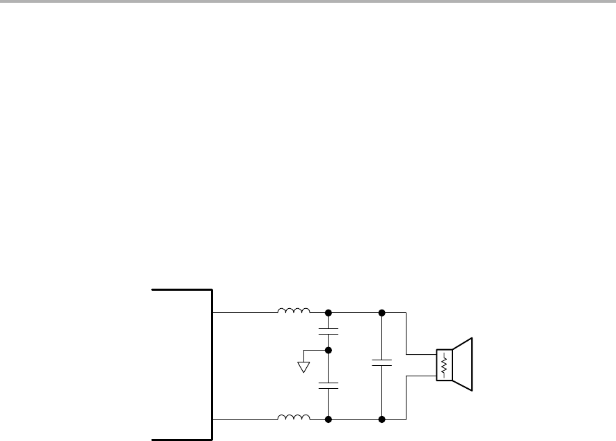
LC filter is shown in Figure 4−9.
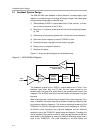
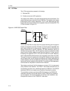
Figure 4−9. APA100 Output Filter
R
(Load)
C2
C1A
C1B
L
L
Output A
Output B
TAS51xx
To limit near-field EMI, the loop area of the output switching path through the
inductor and capacitor must be minimized. To minimize the far-field EMI, filter
each output referenced to a clean ground. Capacitors C1A and C1B filter the
outputs referenced to ground. Capacitor C2 adds differential filtering to
minimize the loop area. Also, 100-nF capacitors need to be placed from each
output terminal (where speaker wires leave the board) to a clean ground.
Increasing the capacitors (C1A, C1B, and C2) lowers the cutoff frequency,
which improves EMI performance but also increases current flow in the filter.
The type of inductor is important for limiting EMI. Multiple winding inductors
can be made small, but the multiple windings start to function capacitively at
a lower frequency and do not attenuate as much of the 100-MHz to 500-MHz
harmonics that are needed to eliminate EMI. For additional EMI suppression,
a ferrite bead can be placed in series with the inductors.
The inductor must have 8 µH of inductance or more at 15 A, for overcurrent
(OC) protection to be effective. The TAS5111 data sheet recommends 5 µH
of inductance, but that is for a switching frequency of 380 kHz. The APA100
switches at 250 kHz and needs more inductance to protect the device.
The modulation scheme used by the APA100 (based on the TPA2001D1
modulation scheme) can be used without a filter if EMI and OC protection
are not important. For more information on the filter−free modulation, see
the application section of the TPA2001D1 data sheet.