


Feedback System Design
4-6
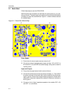
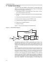
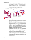
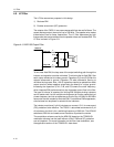
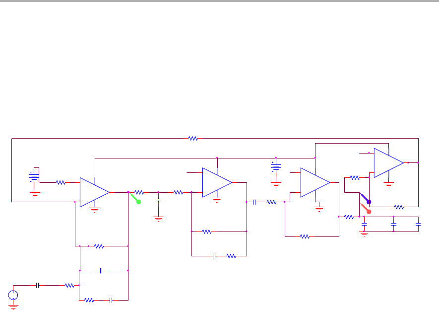
Instead of calculating the bandwidth, PSPICE was used with a linearized
circuit (see Figure 4−5) to simulate and adjust the component values to
approximately 40-kHz bandwidth. Then, Equations 7 and 8 were used to set
the poles and zeros. The first op amp (U1) in the simulation circuit of
Figure 4−5 is the integrator; the second op amp (U2) sets the 80-kHz pole; the
third (U3) adds the gain from the TPA2001D1 and TAS5111 (56 V/V); and the
final op amp (U4) is the divide−by−45 feedback amplifier.
Figure 4−5. PSPICE Circuit for Simulating the Feedback
0
U12A
TLV2464A
3
2
4
11
1
+
−
V+
V−
OUT
R24
1k
U13A
TLV2464A
3
2
4
11
1
+
−
V+
V−
OUT
R121
20
R112
1k
0
R18
1k
filterdivide by 45 in
feedback of APA100
3
C1
1n
V1
1
R16
40k
adds 56V/V of gain from
TPA2001D1 + TAS5111.
Output of this opamp is
simulating output of
TAS5111.
0
R14
2k
0
C25
3.3n
adds 80kHz pole for TPA2001D1
3
R1
100
V3
3
R23
4.7k
0
C26
56p
55
0
U10A
TLV2464A
3
2
411
1
+
−
V+
V−
OUT
R120
10
C10
3
R21
200k
R17
1k
R119
1k
C116
2nF
VDB
0
R133
1k
C27
22p
C21
220p
C24
56p
C117
20u
0
R115
56k
3
VP
0
U11A
TLV2464A
3
2
4
11
1
+
−
V+
V−
OUT
VDB
V2
1.5
3
Integrator for APA100
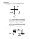
First, resistor R18 was removed to give an open−loop response, with the
APA100 output being simulated by the output of the RC filter after the third op
amp. Taking the gain and phase after the RC filter takes into account the
252−kHz filtering before the feedback op amp.
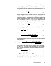
Then, R24 was set low and C25 was adjusted to make the output of the third
op amp equal to the closed−loop gain (27 dB) at 40 kHz; C25 was kept less
than one−tenth of C25. Once the open−loop frequency was approximately 40
kHz, R24 was adjusted to set the zero to 48.2 kHz (needing to stay lower than
the pole of the TPA2001D1). The zero was set much lower than 80 kHz for
compensation, so that the cutoff frequency of the filter before the op amp (R22,
R23, C20, C23, and C24) could be reduced from 400 kHz to 252 kHz. Resistor
R24 was set to 1000 Ω, and capacitor C25 set to 3.3 nF.
The second pole, Fp from Equation 8, was set to 770 kHz by adjusting
capacitor C21 to 220 pF.
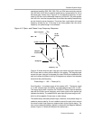
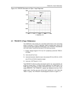
The circuit was simulated to show 40-kHz bandwidth with 49_ phase margin
(see Figure 4−6). The red curve (simulating APA100 output) hits 27 dB at 40
kHz, and at 40-kHz frequency the phase margin (blue curve) is 49_.
The green curve is the output of the integrator. Notice that the green curve’s
slope levels off at 48 kHz, showing that the zero is properly placed. The zero
does not cause the TAS5111 output (red curve) to level off at the zero
frequency because the pole of the TPA2001D1 at 80 kHz keeps the overall
slope constant. The red curves slope increases after 770 kHz due to the
integrator pole from C21.