


Power−Up/Down Sequence
3-3
EVM Operation
Power Up
6) Press and hold the RESET button (S1)
7) Verify correct voltage and input polarity, and set the external power supply
to on.
8) Depress the RESET button (S1).
The EVM begins operation.
9) Adjust the signal source level as needed.
10) Hold RESET button (S1) while powering down
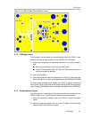
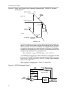
3.2 Power−Up/Down Sequence
The RESET pin of the TAS5111 needs to be held low while turning on power.
This enables the feedback loop to get settled and avoids a loud pop. An RC
filter was placed on the board to help with this, but for optimal pop perfor-
mance, hold the RESET button (S1) during start-up. The RESET button
should also be held during power-off to reduce power-off pop.
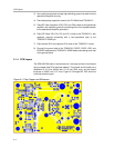
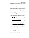
3.3 Reset Button/Mute
The reset button (S1) controls the RESET pin of the TAS5111. This pin keeps
the outputs of the TAS5111 from switching and can also be used as a mute
button. This is valuable because it allows the feedback loop to stay active and
minimizes the pop going into and coming out of mute.
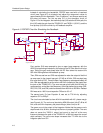
3.4 Error Signals
The APA100 board has test points to monitor the error signals from the
TAS5111. Test points SD and OTW gives TAS5111 state information as
described in Table 3−1.
Table 3−1.TAS5111 Error Decoding
OTW SD DESCRIPTION
0 0 Overtemperature error ( Tj>150_C )
0 1 Overtemperature warning ( Tj >125_C )
1 0 Overcurrent (>8 A) or undervoltage (GVDD < 7 V) error
1 1 Normal operation, no errors/warnings