


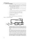
TPA2001D1 (Class-D Modulator)
4-8
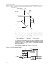
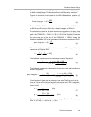
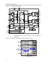
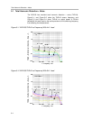
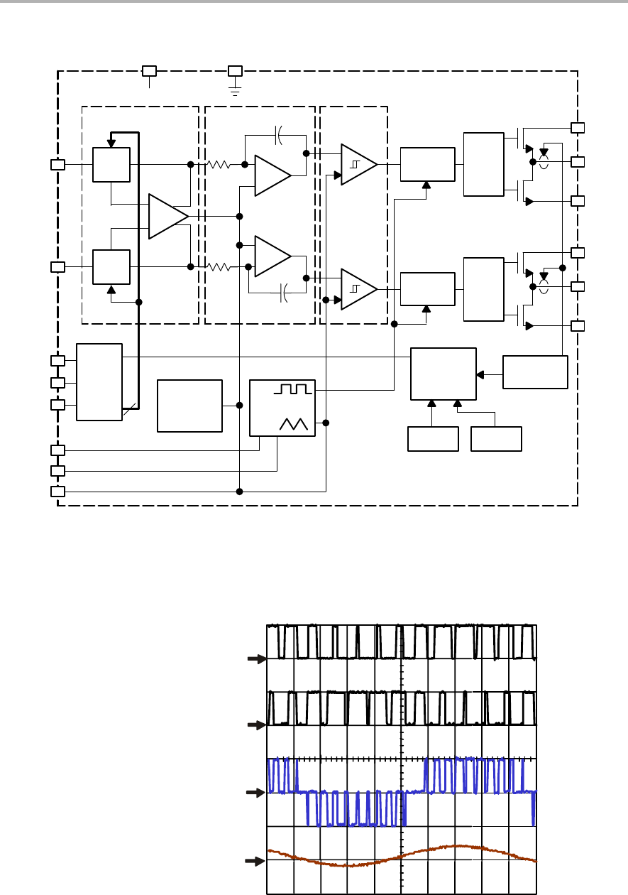
Figure 4−7. TPA2001D1 Block Diagram
_
+
Gain
Adj.
_
+
+
_
cmv
Gain
Adj.
Rs2
Rs1
_
+
_
+
Cint2
Cint1
_
+
Deglitch
Logic
Deglitch
Logic
ComparatorIntegratorPre-Amp
Gate
Drive
Gate
Drive
TTL
Input
Buffers
2
SDZ
Gain
Biases
and
References
Ramp
Generators
Startup
Protection
Logic
OC
Detect
Thermal VDDok
VDD
VDD AGND
INN
INP
SDZ
GAIN1
GAIN0
COSC
ROSC
BYPASS
PVDD
OUTN
PGND
PVDD
OUTP
PGND
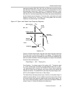
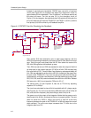
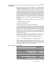
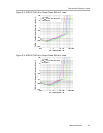
Figure 4−8 shows the output PWM signal and the input signal of the
TPA2001D1.
Figure 4−8. TPA2001D1 Inputs and Outputs With 20−kHz Sine Wave
Ch1: 3V/Div Ch2: 3V/Div Ch3: 3V/Div Ch4: 1V/Div
V
OUT+
CH1
V
OUT
Differential
CH3
V
OUT−
CH2
V
IN
CH4
t − Time − 5 ms