Feedback System Design
4-3
Technical Information
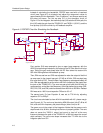
operational amplifier (R22, R23, C20, C23, and C24) was eventually reduced
from 400 kHz to 252 kHz to optimize performance; compensation for this is
discussed later. Notice that in Figure 4−8, the switching frequency of each
output is 250 kHz, but the differential frequency is 500 kHz. The poles greater
than 400−kHz from the low-pass filters do not affect the stability because they
are ten times the corner frequency. The phase from a pole starts at the pole
frequency divided by ten. If the pole is ten times greater than the corner
frequency, the phase margin is not affected.
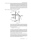
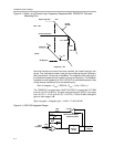
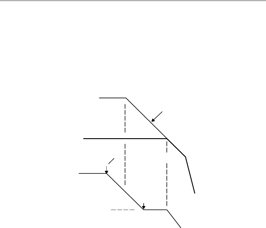
Figure 4−2. Open− and Closed−Loop Frequency Response
Open Loop Gain
Closed Loop Gain
Fc = 40 kHz
0 Degrees
−90 degrees
Phase
Gain − dB
Frequency − Hz
20 dB /
Decade
X
F
P0
F
P0
* 10
F
P0
10
X
X
Low Pass
Filters’ Poles
X
Figure 4−2 shows what the open−loop gain and closed−loop gain would look
like if there were no other poles or delays in the system. The integrator pole
causes the open−loop gain to decrease at a rate of 20 dB per decade after the
pole and causes the phase to shift by 90 degrees over a span of two decades
centered at the pole frequency.
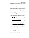
Phase Margin + 180° ) Phase (at Fc)
(1)
From Equation 1, the phase margin of this system is 90_. The device needs
0_ to 180_ phase margin for stability, and most designs require 35_ to 180_.
This design would work. However, the TPA2001D1 has an internal feedback
loop with an 80-kHz corner frequency, which adds a pole to the system and
impedes the stability. The added 80-kHz pole drops the phase margin to 45_,
which is still acceptable if there were no other delays.
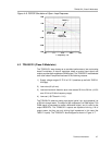
The added delays decrease phase margin; therefore, more phase margin is
needed to ensure stability. A zero is added to cancel the pole, which returns
the overall closed−loop frequency response back to the original design. The
zero can be created by adding a resistor in series with the integrator feedback
resistor. Figure 4−3 shows the effects of the added zero.


