


Feedback System Design
4-2
4.1 Feedback System Design
The APA100 EVM uses feedback to lower distortion, increase supply ripple
rejection, and make the gain not change with supply voltage. This section goes
through the following steps to close the loop.
1) Take feedback at TAS5111 outputs before the LC filter, so that it is unnec-
cary to cancel two poles of the LC filter.
2) Set corner, Fc, frequency to less than half the minimum switching frequen-
cy, Fsw.
3) Add filtering at frequencies greater than 10 times the corner frequency.
4) Add a zero to the integrator to cancel TPA2001D1 pole.
5) Calculate the open−loop gain and set closed−loop gain.
6) Design circuit / component selection.
7) Simulate and adjust.
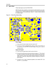
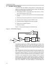
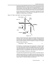
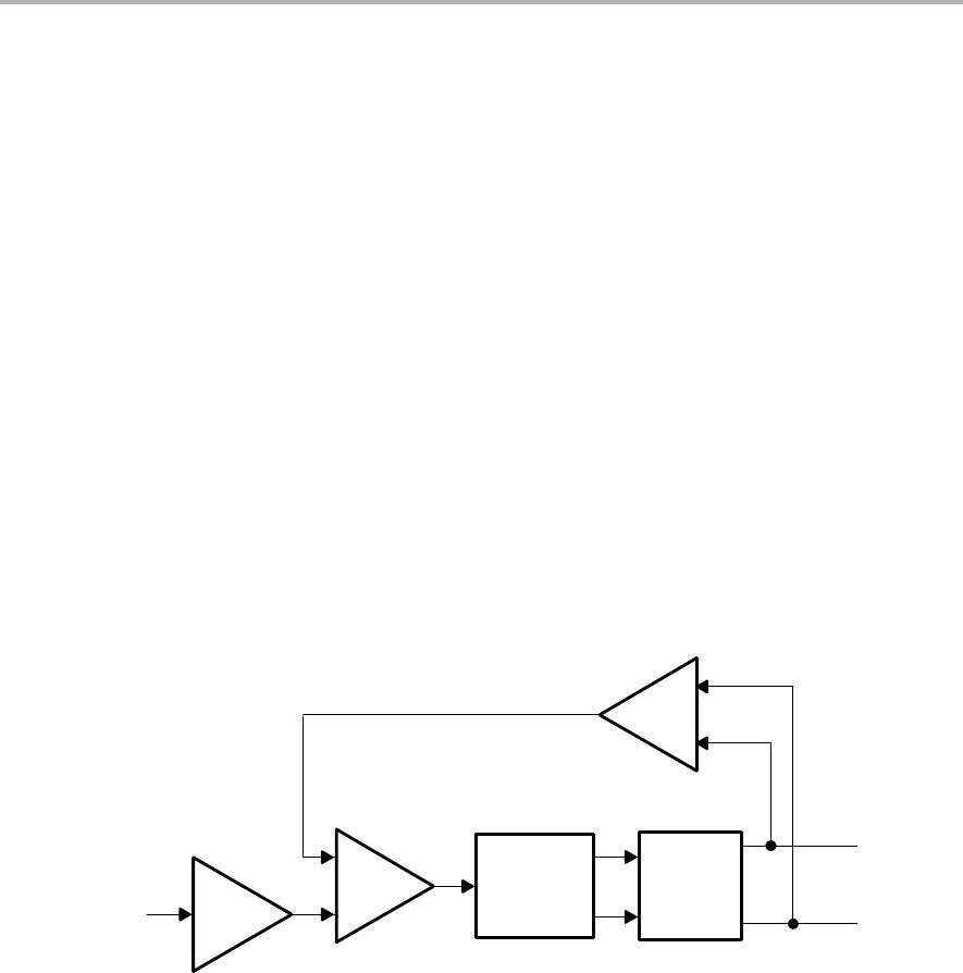
Figure 4−1 shows the block diagram of the feedback loop.
Figure 4−1. APA100 Block Diagram
Audio
Output
Differential to Single -
Ended Converter
Gain
Sum and
Integrate
Analog Input
Class-D
Modulator
TPA2001D1
H-Bridge
(TAS5111)
Gain = 18 dB Gain = A+/3 V
− 33 dB
Audio
Output
The feedback is taken at the TAS5111 outputs before the LC filter. If the
feedback were taken after the LC filter, the two poles caused by the
second−order, low−pass filter would have to be cancelled with zeros in the
integrator. This is difficult and would limit the inductor and capacitor to a tight
tolerance.
When closing the loop, the first thing to choose is the corner frequency. For a
class−D amplifier, the closed−loop corner frequency needs to be less than half
the minimum switching frequency. The minimum switching frequency of the
TPA2001D1 is 200 kHz, limiting the maximum corner frequency to 100 kHz.
An 80-kHz corner frequency was originally designed, but the switching
waveform input to the TPA2001D1 added noise and distortion. Therefore, the
corner frequency was lowered to 40 kHz, and low-pass filters set at 400 kHz
were added in the feedback to reduce the 500-kHz differential signal that is
input to the TPA2001D1. The cutoff frequency of the filter before the