


PCB Layout
2-4
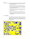
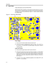
3) Use a split ground plane to keep high switching ground currents from the
operational amplifier circuitry.
4) Place decoupling capacitors close to the TLV2464A and TPA2001D1
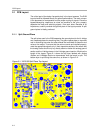
5) Place RC filter capacitors (C20, C23, and C24) close to the operational
amplifier, with capacitor grounds connecting with a low−impedance path
to the operational amplifier ground pin.
6) Place RC filters (R8, R10, C8, and C11) close to the TPA2001D1, with
capacitor grounds connecting with a low−impedance path to the
TPA2001D1 AGND pin.
7) Place resistor R13 and capacitor C18 close to the TPA2001D1 inputs.
8) Connect the ground side of the TPA2001D1 ROSC, COSC, VDD, and
BYPASS components to TPA2001D1 AGND before connecting to the rest
of the ground plane.
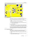
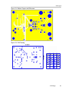
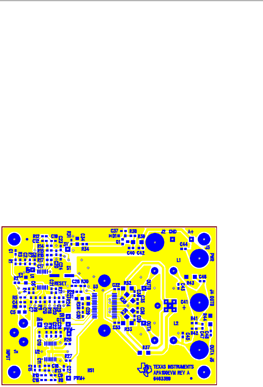
2.1.4 PCB Layers
The APA100 EVM board is constructed on a two-layer printed−circuit board
using a copper-clad FR-4 laminate material. The printed−circuit board has a
dimension of 3.4 inch (86,36 mm) X 2.5 inch (63,5 mm), and the board
thickness is 0.062 inch (1,57 mm). Figure 2−3 through NO TAG show the
individual artwork layers.
Figure 2−3. Top Copper and Silkscreen