


Feedback System Design
4-4
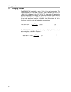
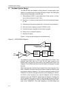
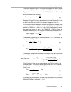
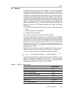
Figure 4−3. Open− and Closed−Loop Frequency Response With TPA2001D1 Pole and
Canceling Zero
Open Loop Gain
Closed Loop Gain
Fc = 40 kHz
0 Degrees
−90 Degrees
Phase
Gain − dB
Frequency − Hz
20 dB /
Decade
X
F
P0
F
P0
* 10
F
P0
10
X
X
X
80 kHz
>400 kHz
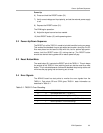
Now that the poles and zeros have been realized, the closed−loop gain can
be set. First, calculate the open−loop gain by multiplying the gain (adding in
dB) of each block, if there was no feedback. The integrator block adds gain of
the feedback impedance/input resistor at the given frequency. The feedback
impedance is the impedance of C24 + R25 (C21 is overlooked because it has
a large enough impedance to be considered open).
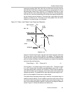
Gain of integrator = Z
C24
+ R25/R18 (Z
C24
= 1/(2π x C24 x f))
The TPA2001D1 has a gain set to 18 dB. The TAS5111 converts the 3-V PWM
to the A+ rail (18 V to 29.5 V). The open−loop gain from the TAS5111 can range
from 18 V/3 V = 6 V/V to 29.5 V/3 V = 9.8 V/V (17 dB to 29 dB). Adding the
gains of each stage in dB:
Open−loop gain = Integrator gain + 18 dB + 17 dB to 20 dB.
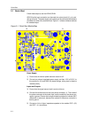
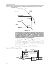
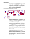
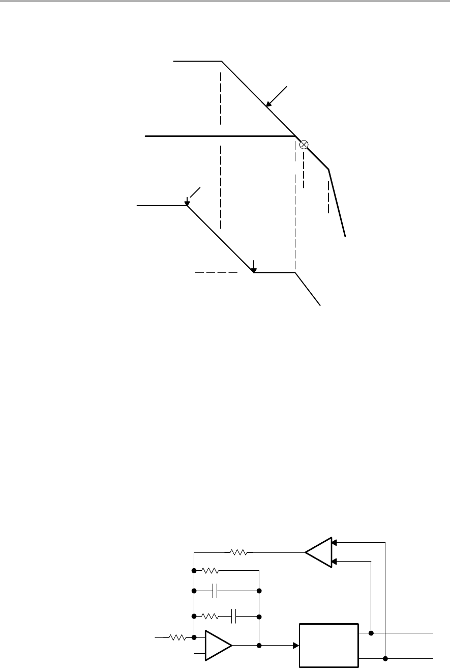
Figure 4−4. APA100 Integrator Design
_
+
MID
R18
R24
C25
C21
R21
R20
− 33 dB
TPA2001D1
+
TAS5111
35 dB
Differential to Single-
Ended Converter
Audio
Output
Input
Amplifier