


Application Notes
29
10.2. Phase-adjustment with the DN9848
To meet the demands of a wide range of situations, the Klark Teknik DN9848 provides two all-pass
filters with complementary control parameters for fine-tuning the phase response on each output.
Although some cross-over filter designs, e.g. Linkwitz-Riley types, are inherently phase-aligned at
cross-over, others such as Butterworth or Bessel responses may require manual phase alignment.
Even Linkwitz-Riley filters may not produce accurate phase coherence when HPF and LPF are
combined to produce a band-pass output. In addition, the phase response of the drive units and
cabinets (especially horn-loaded types) may require compensation to achieve correct acoustic phase,
even if the electrical phase is correct. The DN9848 filters provide straightforward tuning control in all
cases.
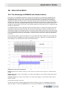
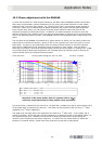
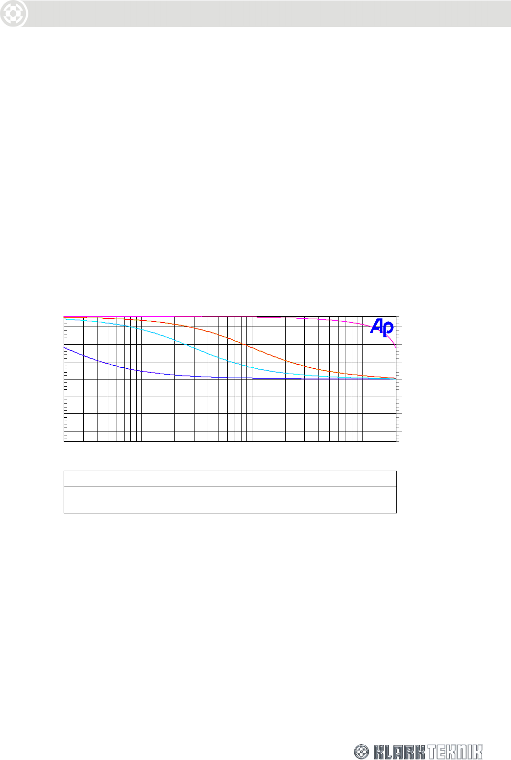
The first filter of the DN9848 is presented as a “phase shifter” for which you can specify a particular
phase shift at a reference frequency, namely a HPF or LPF (typically the cross-over point) or one of
the 6 PEQs. The plots in the graph below show the effect of these controls on the filter response
when set to a 90 phase shift at references points equivalent to 20Hz, 300Hz, 1kHz and 20kHz.
Referring to the figure, the overall response always remains the same shape i.e. tending from +180
at low frequencies to 0 at high frequencies, but is shifted along the frequency axis to achieve the
required phase shift at the specified reference point.
Audio Precision 01/19/01 15:52:4590 deg phase shift @ 20, 300, 1K, 20K
phase.at1
Color Line Style Thick Data Axis
Green Solid 1 Anlr.Phase Left
Yellow Solid 1 Anlr.Phase Right
Yellow Solid 1 Anlr.Phase Left
-150
+150
-100
-50
+0
+50
+100
d
e
g
-150
+150
-100
-50
+0
+50
+100
d
e
g
20 20k50 100 200 500 1k 2k 5k 10k
Hz
Response of the phase shifter filter for a phase shift of 90 at
reference points equivalent to 20Hz, 300Hz, 1kHz and 20kHz
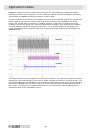
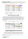
The second filter, presented to the user as an “all-pass filter”, enables the user to set the Order and Q
of the phase shift, at a particular Frequency. The Order can be switched to Off (no filter), 1
st
order
(90 shift) or 2
nd
Order (180 shift).
The graph over the page shows the response of the filter for a 1
st
order shift. In this mode, the Q
control is disabled. As can be seen, the filter behaves in an identical manner to the phase shifter, i.e.
the response tends from +180 at low frequencies to 0 at high frequencies, shifted along the
frequency axis according to the chosen frequency. In effect, this is a phase shifter for which the
frequency is entered directly, rather than being referred to a HPF/LPF or PEQ section.