


Controls, Connectors, Indicators
4
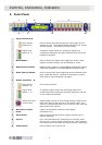
2. FRONT PANEL
1 Input channels A-D
Menu Access
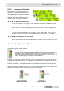
Buttons A-D
Press to access and step through the menu pages for the
respective input. The available pages depend on the current
security setting. The button is lit when active.
Signal Level
Meters A - D
9-segment signal meters for monitoring signal level
(compressor headroom and gain reduction) and clip on the
respective channels.
2 Recall button Press to access the Recall menu page from which a User,
System or Preset memory can be selected for recall.
3 Alphanumeric display Displays menu pages for viewing/defining parameter values.
Values are adjusted via the DATA ENTRY encoders knobs.
4 Home (Set Up) button Press to exit current menu page and return to default Home
page. Press and hold for 1 second to access Set Up menu,
then press to step through Set Up pages.
5 Output channels 1 - 8
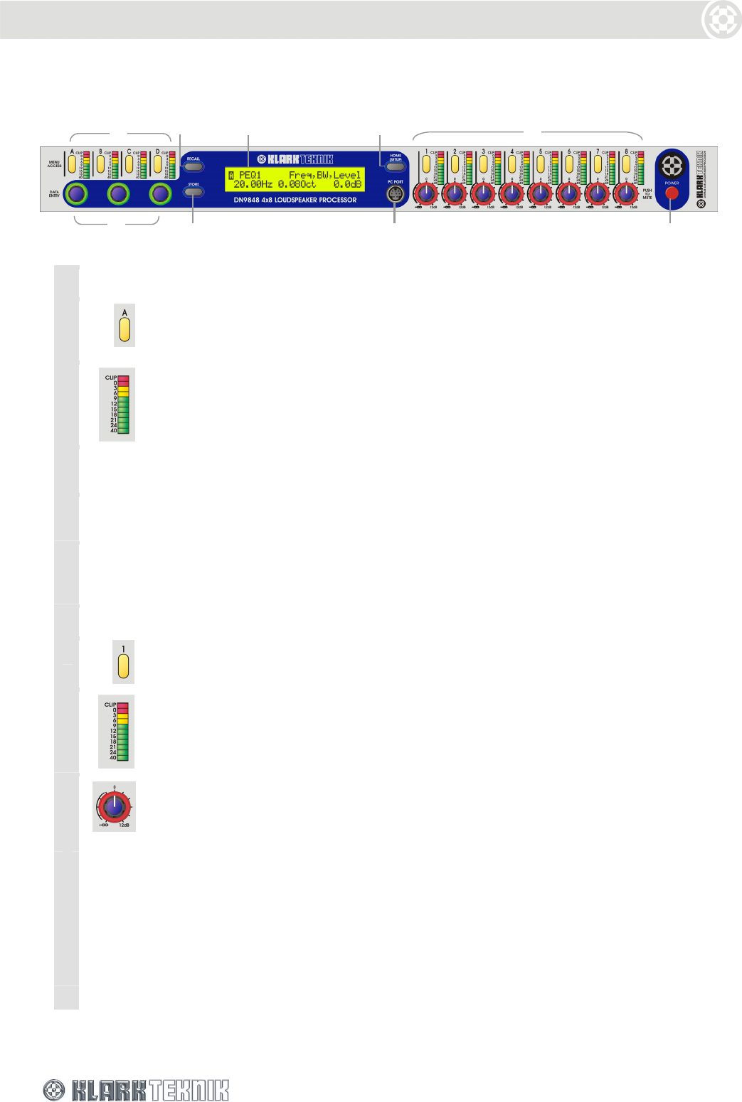
Menu Access
Buttons 1-8
As for input channels.
Signal Level
Meters 1 - 8
11-segment signal meters for monitoring signal level
(compressor/limiter headroom and gain reduction) and clip
on the respective channels.
Output level and
mute control
Potentiometer control for fine-tuning/muting of output level.
Zero level refers to the level set in the output menu. Turn
control to increase/decrease level or press to mute. Red ring
lights when mute is active.
6 Data entry encoder
knobs
Used to set parameter values on menu pages
(see Section 4.1).
7 Store button Press to access the Store menu page for storing User or
System memories.
8 PC port 8-pin mini-DIN socket for connecting to an RS-232 serial
port on a PC or other remote control device. (XLR connector
is provided on the rear panel for remote control via RS-485.)
9 Power button Press to switch the unit on or off.
1 2 3
6
4
5
7 8 9