Output Channels
17
3 Turn the left-hand knob clockwise to access the second sub-menu page. Use the centre knob
to set the compressor attack time (range of 40s – 1ms in 20s steps or 1ms to 100ms in
1ms steps). Use the right-hand knob to set the release time (10ms to 2s in 10ms steps).
To switch the compressor out of the circuit
Set the bypass state on the second page to ‘Yes’. The other settings will be retained for
future use.
6.2.9 Output Limiter
In addition to compression, each DN9848 output has a
limiter to protect any attached equipment being driven
into clip and potentially being damaged. Notably, the
DN9848 uses a special ‘look-ahead’ limiter so that it can
anticipate transient overshoots and act ‘immediately’
(see Application Notes for further details). The limiter threshold can be adjusted to accommodate the
varying requirements of commercial equipment.
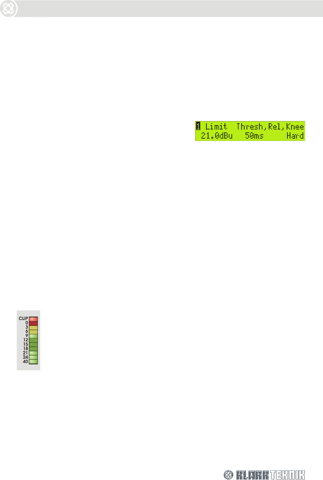
To set the limiter parameters
1 Select a threshold value in the range –10dB to +21dB with the left-hand knob.
2 Use the centre knob to set a release time between 1ms and 100ms.
3 Use the right-hand knob to select a hard or soft knee characteristic for a sharp or gradual cut-
off, respectively.
To switch the limiter out of the circuit
Turn the left-hand knob fully clockwise until the threshold value reads ‘OFF’ (a sharp turn will
leap to the OFF position).
6.3. Monitoring the Output Signal
Each of the eight outputs has an 11-segment signal meter for monitoring internal signal clipping and
output levels that may cause damage to the loudspeaker equipment.
The top CLIP segment monitors the internal signal clipping. It operates independently
of the rest of the meter, lighting if signal clipping is detected at any stage in the
processing circuits regardless of whether the level of the final processed signal is above
or below the compressor and/or limiter thresholds. Hence, the audio engineer has full
visibility of any internal signal clipping that may result in audio distortion.
The 0 to - 40 signal meter is primarily designed to monitor the output level with respect to excessive
levels that may cause damage to the onward loudspeaker equipment. To do this is uses a dual-
purpose scale that refers the signal level to both limiter threshold and compressor threshold, as
illustrated and described overleaf.
