


Output Channels
14
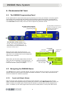
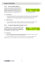
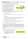
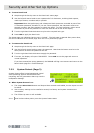
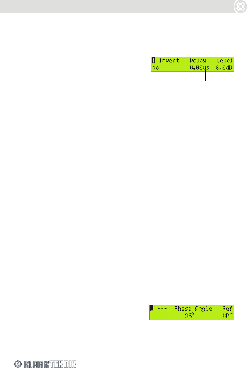
6.2.4 Signal Invert, Delay and Output Level (Page 3)
Each output can be phase inverted by 180
º
(separate
to the phase-alignment for cross-over), delayed for
system alignment and the level attenuated or boosted.
Delay can be specified in terms of time or distance, as
preferred. The unit of measurement is changed in the
Set Up menu (see Section 7.6).
The Level entered here sets the baseline output level,
i.e. the ‘zero’ value, for the rotary Output Gain
controls. For example, if the Level is set to 6dB, the 0
represents 6dB. Turning the rotary Gain Control
right/left will increase/decrease the level in a
proportional manner beyond 6dB (it is not directly additive since the gain is limited to +12dB).
Hence, the Output Gain controls enable fine-tuning during a performance while the baseline output
level is retained as a standard setting for future use.
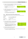
To invert the output signal
Turn the left-hand knob clockwise until the Invert field reads ‘Yes’. The default setting is ‘No’
inversion.
To set the delay
Turn the centre knob slowly for step increments, or sharply to leap to the bottom/top of the
range (1-2 sharp turns covers the whole range). The range is 0 to 1ms in steps of 20.83s
and 1ms to 300ms in steps of 0.01ms, or the equivalent in metres or feet.
To set the base level for the front panel Gain control
Turn the right-hand knob. The range is –40dB to +12dB in steps of 0.1dB, with an OFF
position just ‘below’ –40dB. Setting the gain to OFF will mute the input signal.
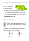
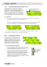
6.2.5 Phase Adjustment (Pages 4 and 5)
To meet the demands of a wide range of situations, the Klark Teknik DN9848 provides two all-pass
filters with complementary control parameters for fine-tuning the phase response on each output,
e.g. for alignment at cross-over. The first filter is presented as a “phase shifter” for which you can
set a specific phase shift at a reference frequency, eg. the HPF or LPF (typically the cross-over point).
The second filter enables a 1
st
or 2
nd
order phase shift to be applied at a chosen frequency. With 2
nd
order, the phase shift window can be shaped, i.e. you can adjust the steepness of the transition by
setting the Q value.
For detailed information on how these filters modify the signal, please refer to the Application Notes
section.
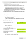
To set a precise phase shift at a reference frequency
1 Step to the Phase Angle/Ref page shown right.
2 Turn the centre knob to select a phase angle
between 0
º
and 180
º
. Turn the right-hand knob
to set the reference frequency to HPF, LPF or
one of the six PEQs (set in the subsequent
Output menu pages).
Delays can be set in
seconds, metres, or feet.
This level sets the
baseline for the rotary
Output Gain control