


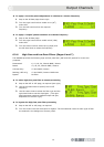
Input Channels
11
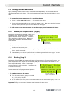
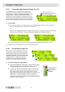
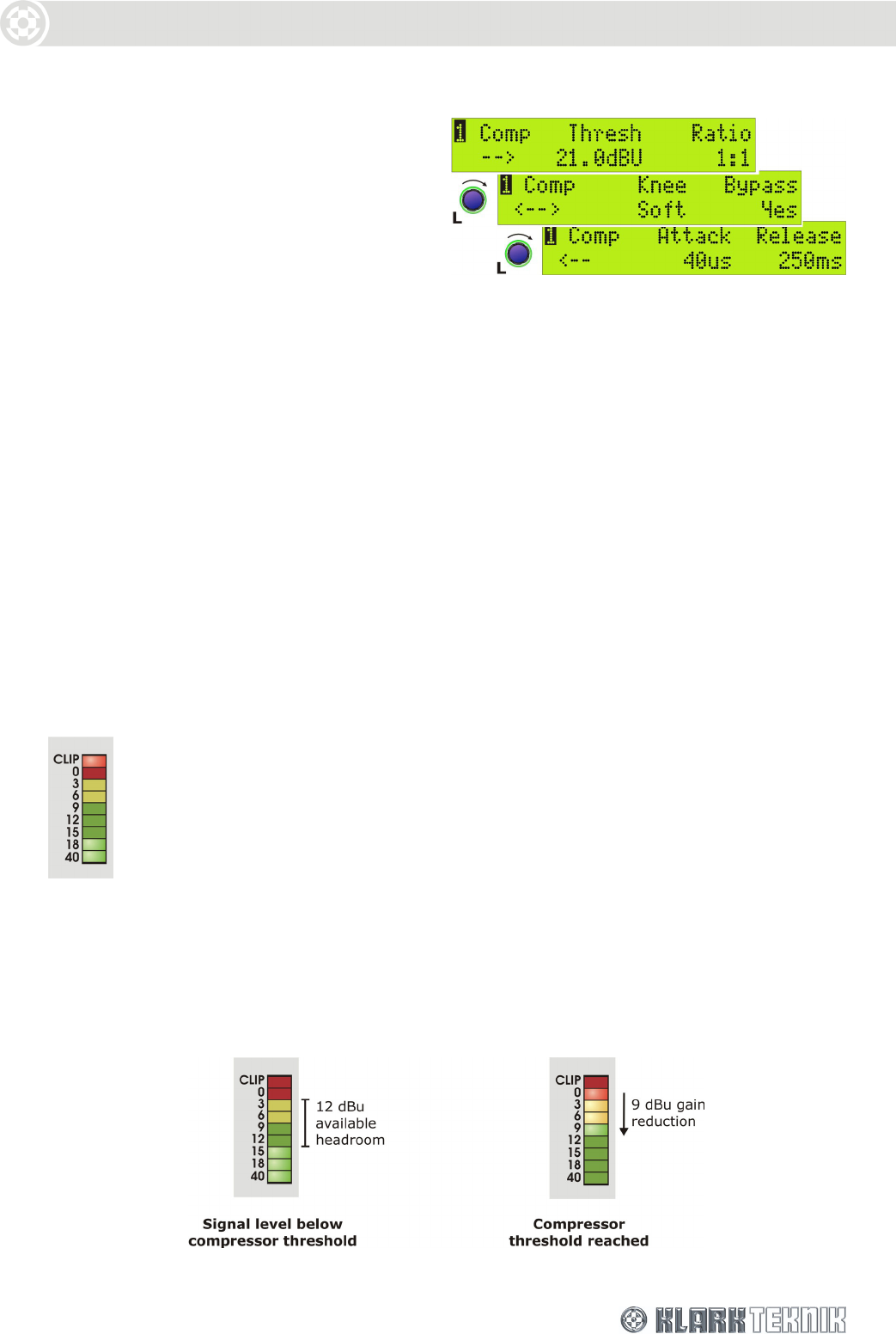
5.2.5 Compression (Page 14)
Each input has an independent full-range
compressor to improve the dynamics of the
incoming signal levels. The compressors are
variable ratio and can be set to a hard knee
characteristic for a sharp gain reduction
response at the compression threshold, or
soft knee for a more ‘musical’ response.
To set the compressor parameters
1 On the first compressor menu page, use the centre knob to select a threshold value in the
range –10dB to +21dB, and the right-hand knob to set a ratio from 1:1 to 5:1.
2 Turn the left-hand knob clockwise to access the first sub-menu page. Use the centre knob to
select a hard or soft knee characteristic and the right-hand knob to set the bypass state to
‘No’ so that the compressor is included in the signal path.
3 Turn the left-hand knob clockwise to access the second sub-menu page. Use the centre knob
to set the compressor attack time (range of 40s – 1ms in 20s steps or 1ms to 100ms in
1ms steps). Use the right-hand knob to set the release time (10ms to 2s in 10ms steps).
To switch the compressor out of the circuit
Set the bypass state on the second compressor page to ‘Yes’. The other settings are held for
future use.
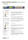
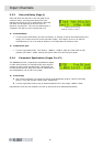
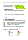
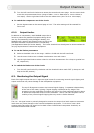
5.3. Monitoring the Input Signal
Each of the four inputs has a 9-segment signal meter for monitoring the internal signal clipping and
compressor headroom or gain reduction.
The top CLIP segment monitors the internal signal clipping. It operates independently
of the rest of the meter, lighting when signal clipping is detected at any stage in the
processing circuits, regardless of whether the input level is above or below the
compressor and/or limiter thresholds. Hence, the audio engineer has full visibility of
internal signal clipping that may result in audio distortion.
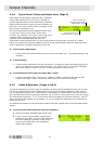
The 0 to - 40 signal meter monitors the input level on a relative scale, where the 0 segment is set at
the specified compressor threshold. For example, if the threshold is set to +9dBu then the input
signal meter 0 segment is set at 9dBu true value, and a signal of –3dBu registers as 12dBu below the
threshold (below left). Thus, when the signal level is below the threshold, the meter indicates the
headroom.
When the signal level reaches the threshold, i.e. the red 0 segment lights, the meter ‘flips’ and reads
downwards to show the amount of gain reduction applied to the signal.