Output Channels
15
To apply a 1st order phase adjustment in relation to a chosen frequency
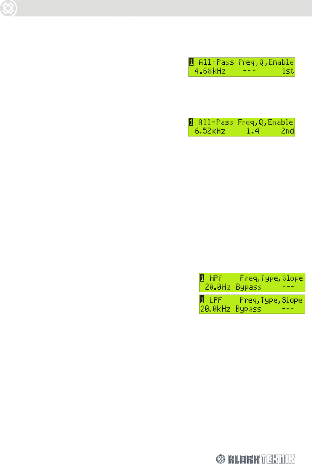
1 Step to the All-Pass page shown right.
2 Turn the right-hand knob to enable a 1st (90
º
)
order shift.
3 Turn the left-hand knob to the required
frequency.
To apply a ‘shaped’ phase transition at a chosen frequency
1 Step to the All-Pass page.
2 Turn the right-hand knob to enable a 2nd (180
º
)
order shift.
3 Turn the centre knob to select the Q (slope) and
the left-hand knob to select the frequency.
6.2.6 High Pass and Low Pass Filters (Pages 6 and 7)
The DN9848 provides the following high and low pass filter (HPF and LPF) options for cross-over
purposes:
Butterworth 6, 12, 18, 24, 36 and 48dB / Octave
Bessel 12, 18, 24, 36 and 48dB / Octave
Linkwitz Riley 12 and 24dB / Octave
Peaking (HPF only) 12 and 24dB / Octave 0-6dB Gain
Bypass No Filter
To add a high/low pass filter to output processing
1 Step to the HPF or LPF page, as required (see right).
2 Use the left-hand knob to specify the cut-off
frequency.
3 Use the centre knob to select the filter type and the
right-hand knob to set the slope/gain. (The right-
hand parameter switches between slope and gain,
dependent on the filter type).
To bypass the high/low pass filter processing
1 Step to the HPF or LPF page, as required.
2 Turn the centre knob anti-clockwise to ‘Bypass’. The last selected values for each type of filter
are retained in the background for easy recall.


