


12
masterpage:Leftfilename[\\Win-35\logitecmo\422958711MDSJE640CED\01GB03OPE-CED.fm]
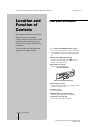
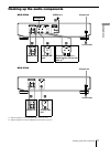
Hooking up the audio components
Getting Started
model name1[MDS-JE640] model name2[MDS-JE440]
[4-229-587-11(1)]
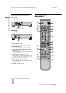
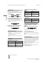
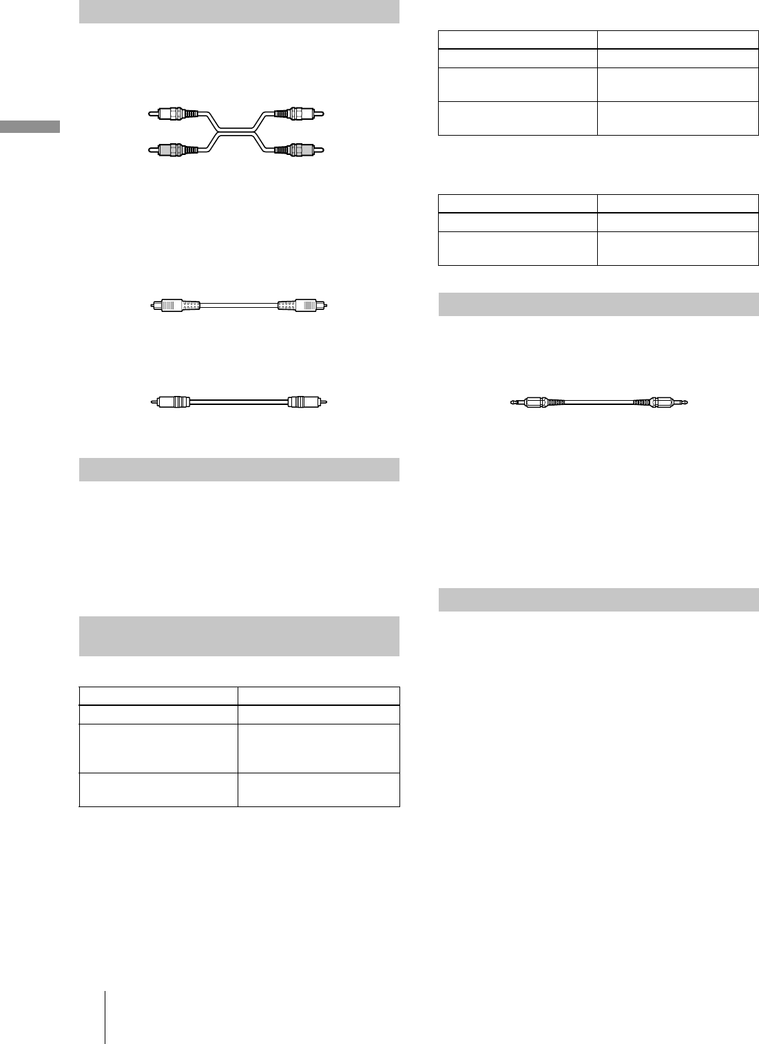
A
Audio connecting cords (2) (supplied)
When connecting an audio connecting cord, be sure to match the
color-coded pins to the appropriate jacks: white (left) to white
and red (right) to red.
B
Optical cables (2 for MDS-JE640 European models/3
for all other models) (only one supplied)
•
When connecting an optical cable, take the caps off the
connectors and insert the cable plugs straight in until they click
into place.
•
Do not bend or tie the optical cables.
C
Coaxial digital connecting cable (for MDS-JE640
European models only) (1) (not supplied)
•
Turn off the power of all components before making any
connections.
•
Do not connect any AC power cord until all the
connections are completed.
•
Be sure the connections are firm to prevent hum and
noise.
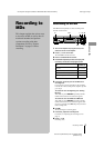
For MDS-JE640 European models
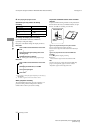
For MDS-JE640 (except for the European
models)
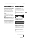
For MDS-JE440
To connect a CONTROL A1
ΙΙ
compatible
component
D
Monaural (2P) mini-plug cables (2) (not supplied)
For details, see “Using the CONTROL A1
ΙΙ
control
system” on page 44.
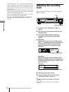
To connect the AC power cord
Connect the AC power cord of the deck to a wall outlet.
Note
If you use a timer, connect the AC power cord to the outlet of the
timer.
When you turn on the MD deck and there is no MD in the
deck, demonstration mode is activated automatically after
about ten minutes. To deactivate the demonstration mode,
press any button on the deck or on the remote.
z
To turn off the demonstration mode
Press
x
and CLEAR simultaneously when there is no MD in the
deck.
“Demo Off” appears in the display.
To turn on the demonstration mode again, perform the same
procedure described above.
“Demo On” appears in the display.
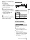
Required cords
Hookup considerations
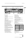
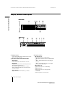
Jacks (connectors) for connecting audio
components
Connect To the
Amplifiers ANALOG IN/OUT jacks
CD players or DBS tuners
DIGITAL COAXIAL IN jack
or DIGITAL OPTICAL IN
connector
Digital amplifiers, DAT decks,
or another MD deck
DIGITAL OPTICAL IN/OUT
connectors
White (L)
Red (R)
White (L)
Red (R)
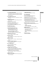
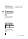
Connect To the
Amplifiers ANALOG IN/OUT jacks
CD players or DBS tuners
DIGITAL OPTICAL IN
1)
connector
1) There is no distinction of IN1 and IN2 connectors.
Digital amplifiers, DAT decks,
or another MD deck
DIGITAL OPTICAL IN
1)
/
OUT connectors
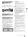
Connect To the
Amplifiers ANALOG IN/OUT jacks
CD players or DBS tuners
DIGITAL OPTICAL IN
connector
Other connections (MDS-JE640 only)
Demonstration mode