


Chapter 2 Names and Functions of Parts
28
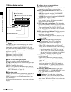
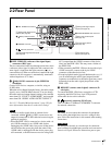
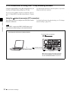
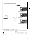
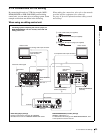
2-2 Rear Panel
ACHTUNG
Aus Sicherheitsgründen nicht mit einem Peripheriegerät-
Anschluss verbinden, der zu starke Spannung für diese
Buchse haben könnte. Folgen Sie den Anweisungen für
diese Buchse.
e AUDIO MONITOR OUT connector (RCA-pin)
This outputs an audio signal for monitoring.
The monitored channel is selected by the combination of
the AUDIO MONITOR SEL button (see page 22) and
MONITOR switch (see page 22).
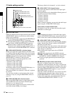
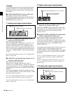
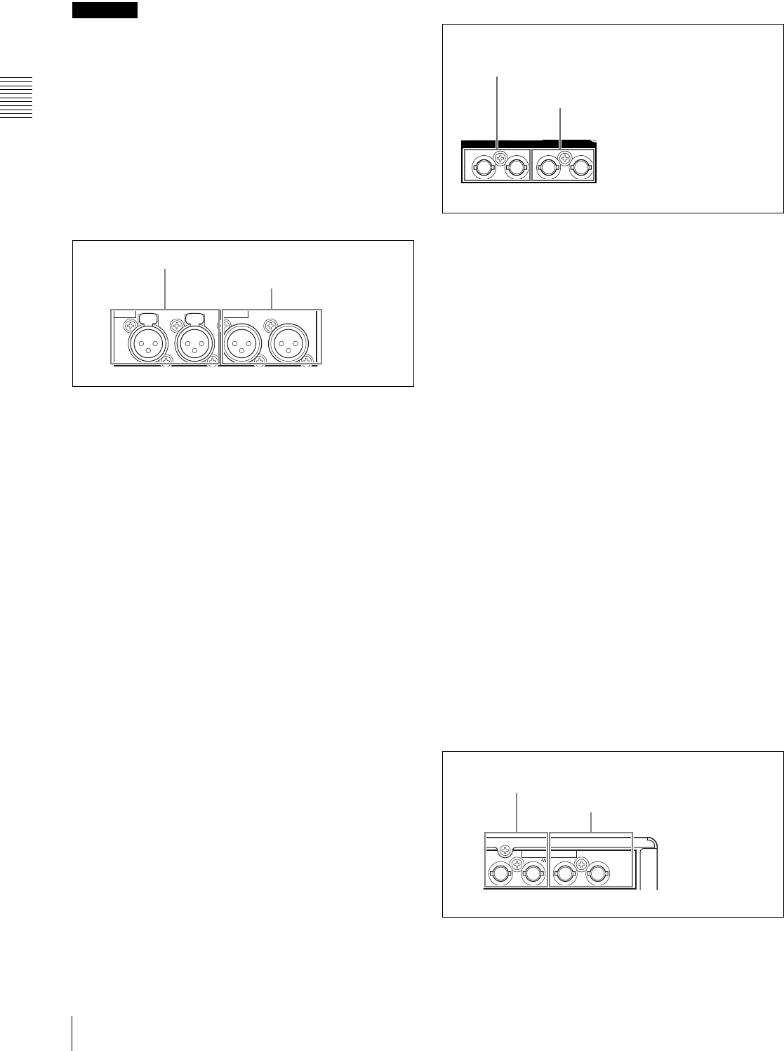
1 Analog audio signal inputs/outputs
a AUDIO IN (analog audio signal input) 1/3, 2/4
connectors (XLR 3-pin, female)
These input analog audio signals.
With the AUDIO INPUT SEL button (see page 22), you
can select whether the signal input to connector 1/3 is
assigned to audio channel 1or 3, and whether the signal
input to connector 2/4 is assigned to audio channel 2 or 4.
You can set the reference input level with the maintenance
menu item “AUDIO CONFIG.” (Factory default setting:
+4 dB)
For details of the maintenace menu, see 8-4 “Maintenance
Menu” on page 124.
b AUDIO OUT (analog audio signal output) 1/3, 2/4
connectors (XLR 3-pin, male)
These output analog audio signals.
When the unit is shipped from the factory, the 1/3
connector is set to audio channel 1, and the 2/4 connector
is set to audio channel 2. You can change these settings
with extended menu item 824 “ANALOG LINE OUTPUT
SELECT.”
You can set the output level with the maintenance menu
item “AUDIO CONFIG.” (Factory default setting: +4 dB)
Non-audio signals are muted.
See 8-3-2 “Extended Menu Operations” (page 120) for
more information about how to make these settings.
For details of the maintenace menu, see 8-4 “Maintenance
Menu” on page 124.
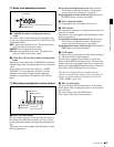
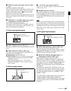
2 Digital audio signal inputs/outputs
a DIGITAL AUDIO (AES/EBU) IN (digital audio
input) 1/2, 3/4 connectors (BNC type)
These input AES/EBU format digital audio signals. The
left connector (1/2) corresponds to audio channels 1 and 2,
and the right connector (3/4) corresponds to audio
channels 3 and 4.
b DIGITAL AUDIO (AES/EBU) OUT (digital audio
output) 1/2, 3/4 connectors (BNC type)
These output AES/EBU format digital audio signals.
When the unit is shipped from the factory, the 1/2
connector is set to audio channel 1/2, and the 3/4 connector
is set to audio channel 3/4. You can change these settings
with extended menu item 827 “AES/EBU AUDIO
OUTPUT SELECT.”
To treat the input and output signals of these connectors as
non-audio signals, set the maintenance menu item
“AUDIO CONFIG”-“NON-AUDIO INPUT” (recording)
and extended menu item 823 “NON-AUDIO FLAG PB”
(playback).
See 8-3-2 “Extended Menu Operations” (page 120) for
more information about how to make extended menu
settings.
See 8-4-2 “Maintenance Menu Operations” (page 126)
for more information about how to make maintenance
menu settings.
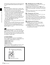
3 Analog video signal inputs/outputs
1/3 2/4 1/3 2/4
AUDIO IN AUDIO OUT
1 AUDIO IN 1/3, 2/4 connectors
2 AUDIO OUT 1/3, 2/4 connectors
1/2IN 3/4 1/2OUT 3/4
DIGITAL AUDIO (AES/EBU)
1 DIGITAL AUDIO (AES/EBU) IN 1/2, 3/4 connectors
2 DIGITAL AUDIO (AES/EBU)
OUT 1/2, 3/4 connectors
12
(SUPER)
VIDEO IN VIDEO OUT
1 VIDEO IN connectors
2 VIDEO OUT 1, 2 (SUPER) connectors