


Chapter 2 Names and Functions of Parts
22
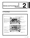
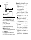
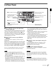
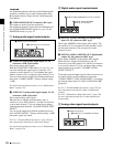
2-1 Front Panel
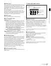
2 Audio settings section
a MONITOR switch
Of the two channels (left and right) selected by the AUDIO
MONITOR SEL button (see next item), selects whether
both or one is monitored.
L: The left channel audio is output from the PHONES jack
and the AUDIO MONITOR OUT connector.
R: The right channel audio is output from the PHONES
jack and the AUDIO MONITOR OUT connector.
MIX: Stereo audio is output from the PHONES jack.
Monaural audio, the left and right channels mixed, is
output from the AUDIO MONITOR OUT connector.
b AUDIO MONITOR SEL (selection) button
Of the up to eight audio signal channels, the audio of the
two channels (left and right channels in the case of a stereo
output) selected by this button can be monitored with the
PHONES jack on the front panel and the AUDIO
MONITOR OUT connector on the rear panel.
Pressing this button cycles through the four of the
following channel combinations.
• Channels 1 (left) and 2 (right)
• Channels 3 (left) and 4 (right)
• Channels 5 (left) and 6 (right)
• Channels 7 (left) and 8 (right)
In the status display section, the MONITOR display (see
page 24) changes to reflect the selection.
The factory default is for channels 1 (left) and 2 (right) to
be selected.
You can select whether to monitor both of the selected
channels or only one, using the MONITOR switch (see
page 22).
c AUDIO METER SEL (selection) button
When using MPEG IMX format in eight-channel mode,
select whether the audio level meters should display
channels 1 to 4 or channels 5 to 8.
Pressing this button toggles the selection, and the audio
level meter channel display also changes.
The factory default is for channels 1 to 4 to be selected.
d AUDIO INPUT CH (channel) button
This selects the channel to which the audio input signal
selection applies.
Pressing this button cycles through the following states of
the audio level meter channel display.
• Channel 1 flashing
• Channel 2 flashing
• Channel 3 flashing
• Channel 4 flashing
• Channels 1 to 4 lit
When a channel is flashing, you can select the audio input
signal using the AUDIO INPUT SEL button.
When audio is in eight-channel mode
On channels 5 to 8, you can input only the audio signals
embedded in an SDI signal.
Note
After completing the selection of the audio input signals
with the AUDIO INPUT SEL button, return the audio level
meters to the state in which all channel indications are lit.
e AUDIO INPUT SEL (selection) button
This selects the input signal to the channel with a flashing
display, that has been selected with the AUDIO INPUT
CH button described above.
Pressing this button cycles the selection of the audio input
signal, and the audio input display above the audio level
meter changes to reflect this.
ANA: Analog audio signal input to the AUDIO IN
connector
SDI: SDI audio signal input to the SDI IN connector
AES/EBU: AES/EBU format digital audio signal input to
the DIGITAL AUDIO (AES/EBU) IN connector
SG: Audio test signal generated by the internal signal
generator
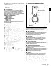
f PHONES jack and volume control knob
The jack is a standard stereo jack. Connect stereo
headphones with an impedance of 8 ohms, to monitor the
audio during recording, playback, and editing. (Non-audio
signals are muted.) The monitored channel is selected by
the AUDIO MONITOR SEL button (see page 22) and
MONITOR switch (see page 22).
Adjust the volume with the knob. You can also cause this
to simultaneously adjust the output volume from the
AUDIO MONITOR OUT connector on the rear panel. To
do this, in the setup menu, set extended menu item 114
“AUDIO MONITOR OUTPUT LEVEL” to “var.”
REC
VARIABLE
PRESET
PB
L
MIX
R
MONITOR
PHONES
TOP
F REV F FWD
END
PREV
NEXT
PLAY
AUDIO
MONITOR SEL
METER SEL INPUT CH INPUT SEL
VID
E
INPU
T
S
T
ALL/CH-1 CH-2 CH-3
40
-60
CH
-
15
40
-60
CH
-
26
40
-60
CH
-
37
40
-60
CH
-
48
1/2
5/6
3/4
7/8
4
MONITOR
1 MONITOR switch
2 AUDIO MONITOR SEL button
3 AUDIO METER SEL button
4 AUDIO INPUT CH button
5 AUDIO INPUT SEL button
6 PHONES jack and volume control knob