


Chapter 8 Menus
113
8-3 Extended Menu
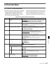
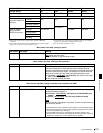
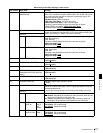
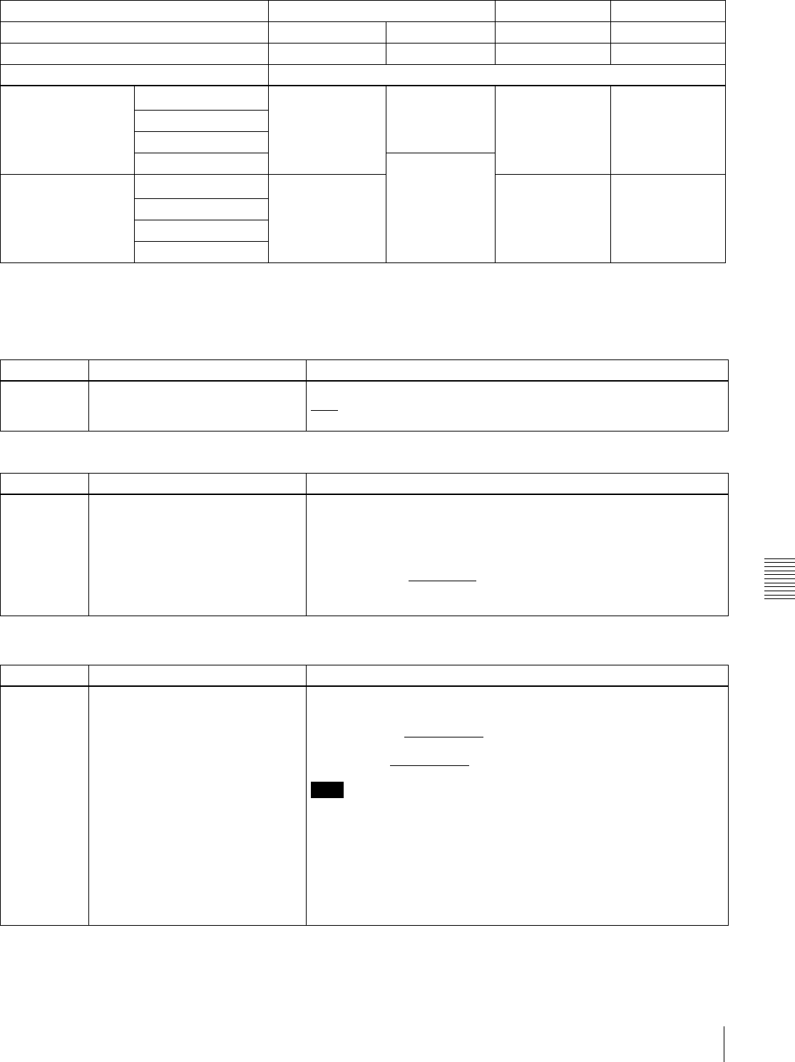
a) Synchronize to the reference signal input to the REF. VIDEO IN
connector.
b) Synchronize to the signal input to the VIDEO IN connector. If no signal is
input to the connector, no synchronization is made.
c) Synchronize to the signal input to the SDI IN connector. If no signal is
input to the connector, no synchronization is made.
d) No external synchronization is made.
VIDEO INPUT SEL button setting SDI i.LINK SG
Item 335 setting ref auto ref/auto ref/auto
Item 308 setting STD/N-STD STD/N-STD STD/N-STD STD/N-STD
Operation mode External synchronization status
When a signal is input
to the REF. VIDEO IN
connector
E-E mode
REF
a)
REF
a)
REF
a)
REF
a)
Normal playback
REC button pressed
Recording
SDI IN/Free
c)
When no signal is
input to the REF.
VIDEO IN connector
E-E mode
SDI IN/Free
c)
Free RUN
d)
Free RUN
d)
Normal playback
REC button pressed
Recording
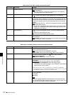
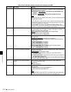
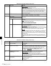
Menu items in the 400s, relating to preroll
Item number Item name Settings
401 FUNCTION MODE AFTER CUE-UP Select the state that the unit goes into after a cuing-up operation.
stop
: Stops (the stop mode).
still: Still playback (in jog and shuttle mode).
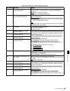
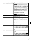
Menu items in the 500s, relating to disc protection
Item number Item name Settings
501 STILL TIMER To protect the disc against shock and vibrations, and to lengthen the life
of the laser diodes, the unit automatically enters standby off mode
whenever a specified time elapses in a disc stop mode (stop mode or the
still picture mode of search mode). This allows you to set the time after
which the unit exits a disc stop mode and enters standby off mode.
0.5 s (0.5 sec)... 8 m (8 min)
... 30 m (30 min): Can be set in the range
from 0.5 seconds to 30 minutes.
off: Do not put into standby off mode.
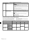
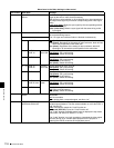
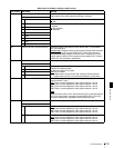
Menu items in the 600s, relating to the time code, metadata, and UMID
Item number Item name Settings
601 VITC POSITION SEL-1
Select a line into which to insert VITC signals for IMX recording signals
a)
and DVCAM playback signals.
b)
12 H (12 line)... 16 H (16 line)... 20 H (20 line) (in 525(U)/525(J) line
modes)
9 H (9 line)... 19 H (19 line)
... 22 H (22 line) (in 625 line mode)
Note
You can insert the VITC signal in two places. To insert it in two places, set
both items 601 and 602.
a)In the IMX format, VITC is inserted as video signals in vertical blanking sections.
Because these signals are output as video signals during playback, the insertion
line can be specified only for recording.
b)In the DVCAM format, VITC is recorded as VAUX (Video Auxiliary) data.
Because VITC is inserted into video signals by the VITC generator only during
playback, the insertion line can be specified only for playback.