


4
MZ-B10
NOTES ON HANDLING THE OPTICAL PICK-UP
BLOCK OR BASE UNIT
The laser diode in the optical pick-up block may suffer electro-
static break-down because of the potential difference generated
by the charged electrostatic load, etc. on clothing and the human
body.
During repair, pay attention to electrostatic break-down and also
use the procedure in the printed matter which is included in the
repair parts.
The flexible board is easily damaged and should be handled with
care.
NOTES ON LASER DIODE EMISSION CHECK
Never look into the laser diode emission from right above when
checking it for adjustment. It is feared that you will lose your sight.
NOTES ON HANDLING THE OPTICAL PICK-UP BLOCK
(LCX-5R)
The laser diode in the optical pick-up block may suffer electro-
static break-down easily. When handling it, perform soldering
bridge to the laser-tap on the flexible board. Also perform mea-
sures against electrostatic break-down sufficiently before the op-
eration. The flexible board is easily damaged and should be handled
with care.
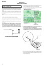
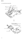
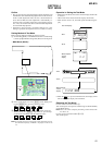
OPTICAL PICK-UP FLEXIBLE BOARD
SECTION 1
SERVICING NOTES
laser-tap
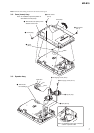
• In performing the repair with the power supplied to the set, re-
moving the MAIN board causes the set to be disabled.
In such a case, make a solder bridge to short SL802 (OPEN
CLOSE) on the MAIN board in advance.
•This set requires the patch data in the nonvolatile memory
(IC802) to be rewritten, when the nonvolatile memory was re-
placed. (See page 30)
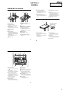
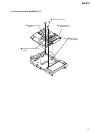
case (upper) assy
MAIN board
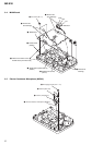
flexible board
(over write head)
• Handle the FLEXIBLE board (over write head) with care, as it
has been soldered directly to the MAIN board.
In repairing the component side of MAIN board, connect the
FLEXIBLE board (over write head) and the MAIN board with
the lead wires in advance.
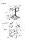
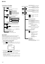
IC801
*
CSP(Chip Size Package)
SL802
(OPEN/CLOSE)
SL802
(OPEN/CLOSE)
– MAIN Board (Side B) –