


Location and Function of Parts
Chapter 1 Overview
14
EN
Chapter 1 Overview
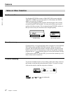
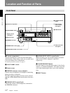
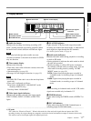
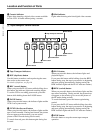
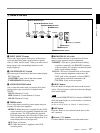
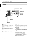
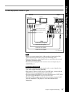
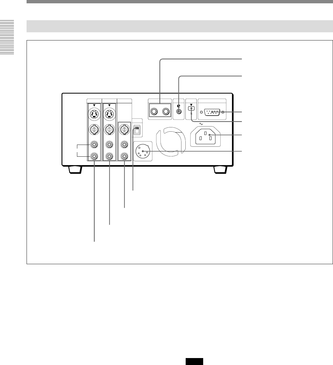
Rear Panel
INPUT OUTPUT
MONITOR
CH-1
CH-2
CH-1/3
CH-2/4
CH-1/3
CH-2/4
CONTROL S
IN OUT
LANC DV
IN/OUT
REMOTE
RS232C
SYNC
DC IN 12V 2.0A
INT
EXT
AUDIO
VIDEO
S VIDEO
AC IN
1 INPUT jacks
Input video and audio signals. To connect a VCR
equipped with the S VIDEO OUT jack, use the
S VIDEO jack on this VCR.
2 OUTPUT jacks
Output video and audio signals. To connect a VCR
equipped with the S VIDEO IN jack, use the S VIDEO
jack on this VCR.
3 MONITOR jacks
Output video and audio signals for monitoring.
4 SYNC switch
Selects the reference signal. The video signal is locked
to V-sync or H-sync, but not locked to sub-career. The
sync phase is not adjusted. The video signal is not
locked to DV input.
INT: Selects the playback signal on this VCR as the
reference signal.
EXT: Selects the input video signal from the external
equipment connected to this VCR as the reference
signal.
Notes
• The picture and the sound may be distorted if:
– You set the SYNC switch during playback.
– The analog signal is input from the INPUT jacks
during playback with the SYNC switch set to EXT.
• If the SYNC switch is set to EXT during playback,
the INPUT SELECT button does not work.
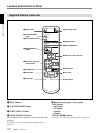
1 INPUT jacks
2 OUTPUT jacks
3 MONITOR jacks
4 SYNC switch
5 CONTROL S jacks
6 LANC jack
8 DV jack
7 REMOTE connector
9 AC IN connector
0 DC IN connector