


Chapter 1 Overview
Chapter 1 Overview 11
EN
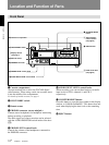
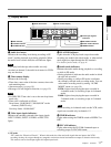
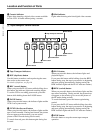
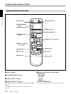
1 Display section
1 Audio level meter
Indicates the recording level during recording or EE
mode
1)
and the playback level during playback. When
the audio level exceeds 0 dB, the red indicator lights.
Note
If you play back the tape whose audio was only
recorded on channel 2, the audio level meter for CH2/4
may not function.
2 Time counter display
Indicates the following:
• Time data: count value of the time counter, time code
and remaining time
• Alarm messages (see page 36)
• Messages for self-diagnosis function (see page 39)
Notes
• For DSR-20P: Time code is set to the non drop frame
mode only.
• Time code is indicated as follows:
Drop frame: “00:00.00:00” (“00:00,00:00” on the
monitor) (DSR-20 only)
Non drop frame: “00:00:00:00”
3 Video input signals indicators
Indicates the currently selected video input signals.
INPUT VIDEO, INPUT S VIDEO or INPUT DV
lights.
4 NS AUDIO indicator
Lights when the VCR plays back a tape whose audio
recording was made in the unlock mode, or when unlock
mode signals are input through the DV terminals.
For details of unlock mode, see page 41.
5 Audio mode indicators
Indicates the audio mode during playback or recording
or while in EE mode.
• During playback it indicates the audio mode in which
the tape was recorded.
• During recording or while in EE mode, it indicates
the currently selected audio recording mode. You can
select audio recording mode by setting “AUDIO
MODE” menu (see page 34).
Fs32k: Lights when playing the tapes recorded in
4-channel mode, or recording a tape in 4-channel
mode.
Fs48k: Lights when playing the tapes recorded in
2-channel mode, or recording a tape in 2-channel
mode.
Note
When recording in 4-channel mode on this VCR, audio
signals are recorded only in channels 1/2.
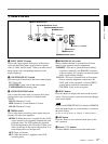
6 TIMER indicator
Lights when setting the TIMER switch to REPEAT or
REC.
7 DVCAM indicator
Lights when using the DVCAM-formatted tapes or
recording a tape on DVCAM format.
........................................................................................................................................................................................................
1) EE mode
“EE” stands for “Electric to Electric”. When in this mode, the video and audio signals that are input to the VCR’s
recording circuitry do not pass through any magnetic conversion circuits but instead are output via electric circuits only.
This mode is used to check input signals and adjust input levels.
CH 1/3 CH 2/4
–
24
12
6
0
Mini
HOURS MINUTES SECONDS FRAMES
TIMER INPUT DV
S VIDEO
NS AUDIO
Fs32k Fs48k
9 Mini indicator
1 Audio level meter 2 Time counter display
3 Video input signals
indicators
4 NS AUDIO indicator
5 Audio mode indicators
6 TIMER indicator7 DVCAM indicator
8 Cassette indicator