


Location and Function of Parts
Chapter 1 Overview
10
EN
Chapter 1 Overview
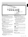
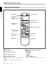
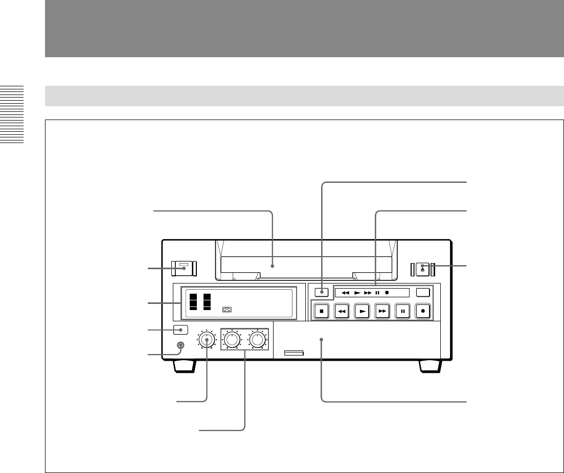
Front Panel
DUP
INPUT
SELECT
TC
TAPE
REMAIN
COUNTER
COUNTER
SELECT
CH-1/2
CH-3/4
MIX
AUDIO
MONITOR
REPEAT
REC
OFF
TIMER
REMOTE
LOCAL
MENU
SET
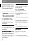
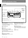
Location and Function of Parts
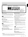
1 Cassette compartment
Accepts standard-size or mini-size DVCAM digital
videocassettes. When using a mini-size cassette, insert
it into the middle of the compartment.
For details of usable cassettes, see page 4.
2 ON/STANDBY switch
3 Remote sensor
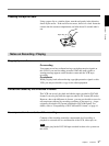
4 PHONES connector (stereo minijack)
Connect stereo headphones for headphone monitoring
during recording or playback.
The audio signal you want to monitor can be selected
with the AUDIO MONITOR switch inside of the door
(3).
5 PHONE LEVEL control knob
Controls the volume of the headphones connected to
the PHONES connector.
6 AUDIO INPUT LEVEL control knobs
When recording, you can use these knobs to set audio
input levels for CH-1 (channel 1) and CH-2,
respectively.
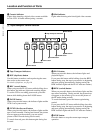
7 COUNTER RESET button
Press this button to reset the tape counter in the display
window to “0:00:00 (0
H00M00S)”. This button does not
work when displaying the time code or the remaining
time.
8 EJECT button
8 EJECT button
2 ON/STANDBY switch
7 COUNTER RESET
button
1Display section
(see page 7)
3 Remote sensor
4 PHONES connector
1 Cassette compartment
2Tape transport
control section
(see page 8)
3Inside of the door
(see page 9)
5 PHONE LEVEL control knob
6 AUDIO INPUT LEVEL control knob