


1-16
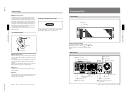
DFS-700/700P
Chapter 3 Basic Operation
3-4
Chapter 3 Basic Operation
5
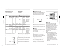
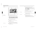
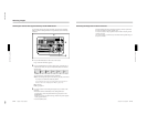
Press button 9 in the pattern/numeric keypad.
The button lights, and this selects the wipe assigned to this button
(pattern number 24). The PATTERN NUMBER display window
shows “0024”.
6
Press the SET button once or twice, so that the EFFECT display
window mode indicator lights.
(If it is already lit, omit this step.)
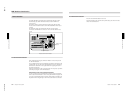
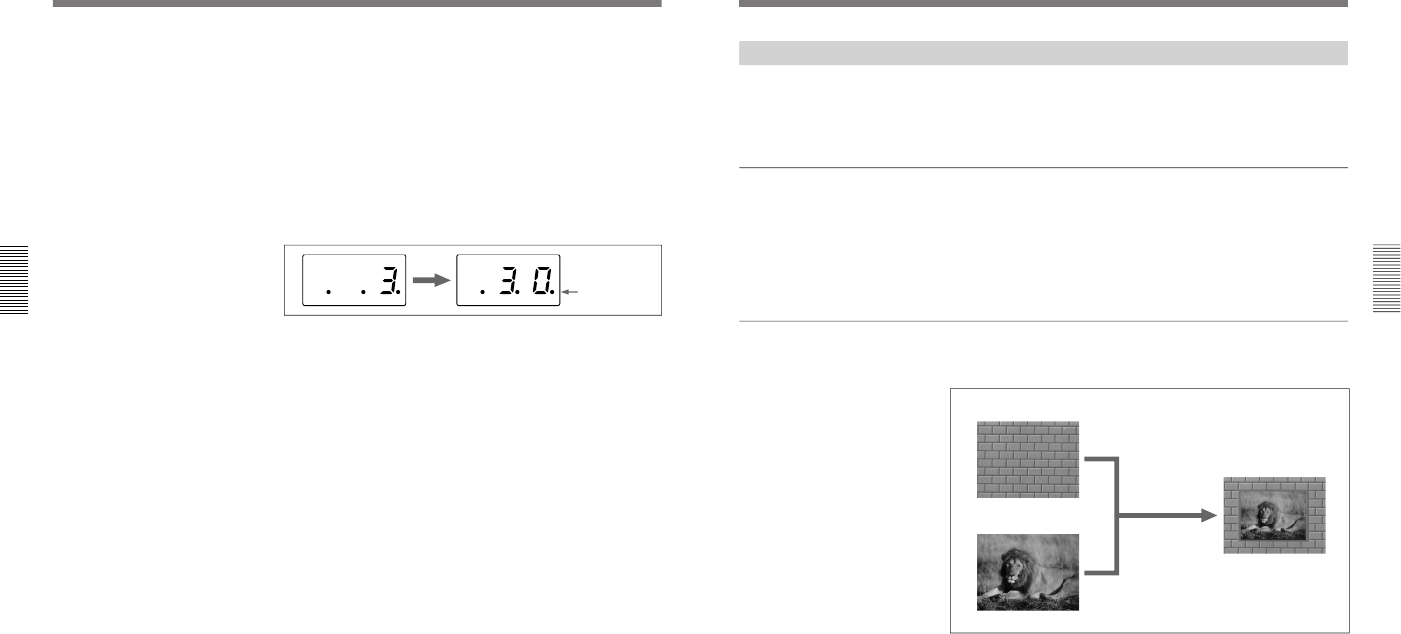
7
In the pattern/numeric keypad, press buttons 3 and 0 in that order.
The TRANS RATE display window shows “.3.0.”.
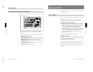
8
Press the ENTER button.
The dots to the lower right of the digits disappear, and the value
entered in step 7 is set as the transition time.
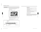
9
Press the EFFECT button, turning it on.
(If it is already lit, omit this step.)
10
Press the AUTO TRANS button.
The wipe is carried out over 30 frames, switching from the background
image to the foreground image.
When the transition completes, BACKGROUND bus button 2 is lit
red, and FOREGROUND bus button 1 is lit amber. This indicates that
as a result of the transition, the video signal connected to the VIDEO
INPUT 2 connector is automatically selected as the background image,
and the video signal connected to the VIDEO INPUT 1 connector as
the foreground image.
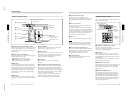
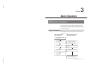
DME Switcher Introduction
<Transition time setting>
Dots appear to
the lower right of
the digits
Chapter 3 Basic Operation
Chapter 3 Basic Operation
3-5
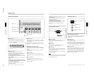
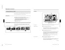
Example Operation (2): Picture-in-Picture
Using the fader lever, we’ll insert the foreground image within the
background image.
We’ll apply a border around the edge of the foreground image.
Setting items
As an example, we’ll set the control panel as follows.
Background image: internal video signal (color background )
Foreground image: video signal connected to the VIDEO INPUT 1
connector
Effect: picture-in-picture (pattern number 1100)
Border: ON
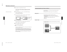
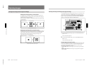
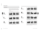
Program output
Executing the above effect produces the following changes in the output
on a program monitor.
Background image
Foreground image
Effect execution
Program output