


1-12
DFS-700/700P
Chapter 2 Location and Function of
Parts and Controls
2-12
Chapter 2 Location and Function of Parts and Controls
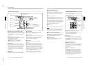
4 HOLD INPUT button
To hold the primary cross-point bus settings and the
auxiliary bus settings (signal selections) fixed when
recalling a snapshot, press this button. When you press
this button, it lights, and when you recall a snapshot,
the system is in the hold input mode. When you recall
a snapshot in this mode, all settings are recreated on
the control panel except those relating to the primary
cross-point bus and the auxiliary bus.
Press the button once more to turn it off and exit the
hold input mode.
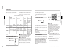
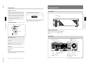
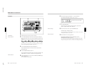
qa Location section
1 LOCATION button
Press this button to use the joystick and Z-knob. When
you press this button, it lights, and enables the joystick
and Z-knob.
Press the button once more to disable the joystick and
Z-knob, and return the effect pattern to its default
position.
Holding down the INITIAL button while pressing this
button returns the setting to its default value.
2 Joystick
Use the joystick to position the effect pattern in the x-
and y-directions.
3 Z-knob
Turn the Z-knob to move an effect pattern in the depth
direction (the z-axis). With this you can change the
effective size of the pattern.
LOCATION
1 LOCATION button
2 Joystick
3 Z-knob
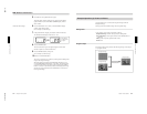
qs 25-pin connector (rear panel)
Use the supplied 25-pin control cable to connect this to
the PANEL connector on the processor unit.
Control Panel
Chapter 2 Location and Function of
Parts and Controls
Chapter 2 Location and Function of Parts and Controls
2-13
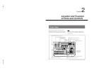
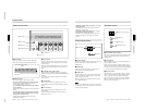
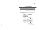
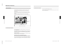
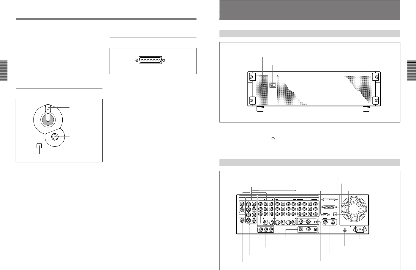
Processor Unit
Front Panel
Power indicator
Power switch
Power switch and indicator
This powers the unit on and off. Press the “
” side of
the switch to power on, and the “
” side to power off.
When the power is on, the power indicator lights
amber.
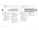
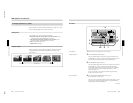
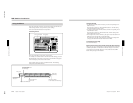
Rear Panel
1 PGM OUT connectors
1
3
1
2
1
2
2
1
3
4
5
6
7
8
21
Y
COMPOSITE
PGM OUT
CLEAN
OUT
OPTION
SDI INPUT PGM OUT
BLACK BURST OUT
VIDEO INPUT
COMPONENT
S VIDEO
COMPONENT/COMPOSITE
COMPONENT
DIGITAL I/O
ANALOG I/O
AC IN
2
R-Y
PVW
B-Y
65
Y/V
R-Y
B-Y
87
6/2 5/1
Y
R-Y
B-Y
8/4 7/3
2 1
REF.VIDEO IN
GPI/T
PANEL
TALLY
EDITOR
TERMINAL
DSK KEY IN
ON
OFF
OFF
75Ω
ON
75Ω
8
7 6 5
S VIDEO
(OPTION)
(OPTION)
2 1
2 VIDEO INPUT connectors
3 EDITOR
connector
4 PANEL connector
5 TALLY connector
6 TERMINAL connector
7 CLEAN OUT connector
8 PVW connector
9 BLACK BURST OUT 1 to 3
connectors
q; DSK KEY IN connectors
and 75Ω terminator
switch
qa REF. VIDEO IN connectors and 75Ω
terminator switch
qs GPI/T 1 and 2 connectors
qd U terminal
qf - AC IN connector