


1-7
DFS-700/700P
Chapter 2 Location and Function of
Parts and Controls
2-2
Chapter 2 Location and Function of Parts and Controls
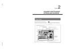
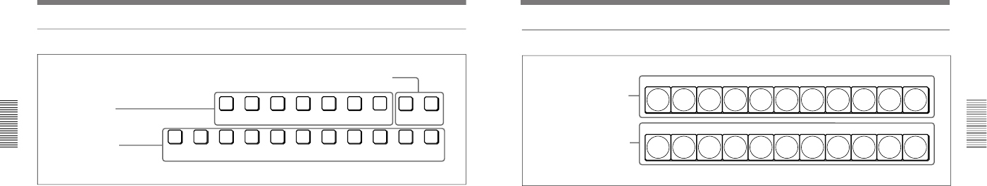
1 Delegation section
1 Delegation buttons
CCR TITLE 1
SOURCE
TITLE 2
SOURCE
DSK
FILL
SUPER BG FRGD 2 MEMORY FRAME FREEZ
BLACK MEMORY INT
VIDEO
12345678
AUXILIARY
2 AUXILIARY buttons
3 Frame memory buttons
1 Delegation buttons
Use these buttons to delegate the input signal
corresponding to the selected AUXILIARY button to
the corresponding function. Pressing one of these
buttons lights it, and the corresponding AUXILIARY
button also lights. Any other previously lit delegation
button goes off.
CCR (color corrector) button: Signal for color
correction
TITLE 1 SOURCE button: Title 1 source signal for
inserting characters and graphics using a title key
TITLE 2 SOURCE button: Title 2 source signal for
inserting characters and graphics using a title key
(only available when the optional BKDF-711 2nd
Channel DME Board is installed)
DSK (downstream keyer) FILL button: Fill signal
for the downstream keyer
SUPER BG (background) button: Background
image for 3D effects
FRGD (foreground) 2 button: One of the
foreground images for 3D effects
MEMORY button: Signal captured in frame
memory
2 AUXILIARY buttons
Select the input signal to be assigned to the function
selected with a delegation button.
Select from the following buttons.
BLACK button: Black burst signal generated by the
internal synchronizing signal generator in this unit
Buttons 1 to 8: Signals input to the VIDEO INPUT 1
to 8 connectors on the rear panel of the processor
unit. You can set the assignment of buttons to
input connectors in the setup menu.
MEMORY button: Signal recorded in frame
memory
INT (internal) VIDEO button: Signal generated by
the internal video signal generator
3 Frame memory buttons
FREEZ button: To capture the input signal selected
by the MEMORY button in the delegation buttons
(excluding the frame memory output signal) as a
freeze image in frame memory, press this button,
turning it on.
Press once more to end the freeze, turning it off.
FRAME button: Select whether to capture a frame
or a field with the FREEZ button. Press this
button, turning it on, to freeze a frame; when the
button is off a field is captured.
When capturing fields, you can select in the setup
menu whether to capture an odd or an even field.
Control Panel
Chapter 2 Location and Function of
Parts and Controls
Chapter 2 Location and Function of Parts and Controls
2-3
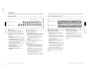
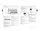
2 Primary cross-point bus section
BACKGROUND
BLACK
MEMORY
INT
VIDEO
12345678
FOREGROUND
BLACK
MEMORY
INT
VIDEO
12345678
2 FOREGROUND bus buttons
1 BACKGROUND bus buttons
1 BACKGROUND bus buttons
Select the image to form the background for an effect.
Select from the following buttons.
BLACK button: Select the black burst signal
generated by the internal synchronizing signal
generator in this unit.
Buttons 1 to 8: Signals input to the VIDEO INPUT 1
to 8 connectors on the rear panel of the processor
unit. Press a button, turning it on, to select the
corresponding signal.
You can set the assignment of buttons to input
connectors in the setup menu.
MEMORY button: Select the signal recorded in
frame memory.
INT (internal) VIDEO button: Select the internal
video signal selected by pressing the MATTES
button in the menu control section. If you hold
down this button and press the DOWN and UP
buttons in the pattern/numeric keypad, the
selected video signal pattern changes.
When the signal on the background bus is output from
the PGM OUT connector on the rear panel of the
processor unit, the button which has been pressed
lights red.
2 FOREGROUND bus buttons
Select the image to form the foreground for an effect
(or the “new” video in a transition).
The functions of the buttons are the same as in the
BACKGROUND bus buttons.
When the signal on the foreground bus is output from
the PGM OUT connector on the rear panel of the
processor unit, the button which has been pressed
lights red. If the signal is not output, the button pressed
lights amber.