


1
DFS-700/700P
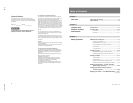
Table of Contents
Manual Structure
Purpose of this manual .............................................................................................. 5
Related manuals......................................................................................................... 5
Contents ..................................................................................................................... 5
1. Operating Instructions
2. Service Overview
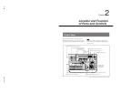
2-1. Installation ...................................................................................................2-1
2-1-1. Operating Environment .............................................................. 2-1
2-1-2. Power Supply Specifications......................................................2-1
2-1-3. Power Supply Cord ....................................................................2-1
2-1-4. Installation Space .......................................................................2-2
2-1-5. Matching Connector and Cable.................................................. 2-3
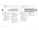
2-1-6. Signal Input/Output .................................................................... 2-4
2-1-7. Rack Mounting ...........................................................................2-7
2-1-8. Installing Optional Board ...........................................................2-9
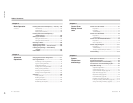
2-2. Removal of Cabinet...................................................................................2-10
2-3. Location of Main Parts ..............................................................................2-11
2-4. Circuit Description ....................................................................................2-12
2-4-1. Processor ..................................................................................2-12
2-4-2. Control Panel ............................................................................2-19
2-5. Replacement of Board ...............................................................................2-21
2-5-1. Replacement of Plug-in Board .................................................2-21
2-5-2. Replacement of Board ..............................................................2-21
2-6. Replacement of Switching Regulator........................................................2-22
2-7. Replacement of DC Fan ............................................................................2-23
2-8. Replacement of Main Parts on Control Panel ........................................... 2-23
2-8-1. Replacement of Fader Assembly .............................................2-23
2-8-2. Replacement of Rotary Encoder ..............................................2-24
2-8-3. Replacement of Joystick ..........................................................2-25
2-8-4. Replacement of Vacuum Fluorescent Display ......................... 2-25
2-9. Fuse/IC Link Replacement........................................................................ 2-26
2-10. Switch, Indicators, and Volume Controls on Board .................................2-27
2-10-1. Control Panel ............................................................................2-27
2-10-2. Processor ..................................................................................2-28
2-11. Error Indication .........................................................................................2-41
2-12. Periodic Inspection ....................................................................................2-42
2-12-1. Periodic Replacement Parts...................................................... 2-42
2-12-2. Filter Cleaning ..........................................................................2-42