


1-105
DFS-700/700P
Index
Index
I-2
Index
Front panel 2-13
FTB indicator 2-4, 3-51
F1 to F5 buttons 2-10
G
Glossary A-66
GPI signals 5-11
GPI button 2-1, 2-7
GPI/T 1 and 2 connectors 2-15
H
HOLD INPUT button 2-12, 4-22
I
Images
auxiliary bus 3-16
background 3-12
foreground 3-12
INITIAL button 2-10
Initializing
assignment of direct pattern 4-2
menu settings 2-10
snapshot 4-24
user program 4-19
user settings 6-10
INT VIDEO button 2-2, 2-3
Inverting polarity
downstream key 3-48
title key 3-35
J
Joystick 2-12
K
Key fill signal
downstream key 3-47
title key 3-35
Key frame 4-3
adding 4-14
assigning to a numeric button 4-16
copying 4-17
deleting 4-15
Keypad 2-1, 2-5
Key signal connections 6-3
Key source signal 3-45
L
LAST X/INS 2-6
LEARN button 2-11, 4-21
LIGHTING button 2-9
Linear effects 4-4
Location and function of parts
and controls 2-1
LOCATION button 2-12, 3-29
Location section 2-1, 2-12
LUM button
DSK section 2-8, 3-46
TITLE section 2-7, 3-35
Luminance key 3-33
M
MASK button
DSK section 2-8, 3-50
TITLE section 2-8, 3-45
Masking
downstream key 3-50
title key 3-44
MATTES button 2-9, 3-57
MEMORY button 2-2, 2-3, 3-16
Menu control section 2-1, 2-7
Menu display 2-10
Menus 3-10
MIX button 2-4
Modifying
edge 3-26
pattern 3-28
N
Nonlinear effects 4-4
N/R button 2-5, 3-52
O
Option board 1-3
Overview 1-1
P, Q
P IN P/RST button 2-6
PAGE button 2-10
PANEL connector 2-14
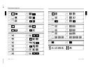
Pattern
changing position and size 3-28
entering pattern number 3-23
image list A-29
modifying 3-31
PATTERN ADJ button 2-10
PATTERN/KEY PAD buttons 2-6, 4-1
PATTERN NUMBER display window
2-5, 3-24
Pattern number specification mode 3-23
Pattern/numeric keypad 2-1, 2-5
PGM OUT connectors 2-14
Picture-in-picture 3-5
Power switch and indicator 2-13
Preread editing 5-14
connections 6-4
Primary cross-point bus section 2-1, 2-3
Primary inputs and signal formats 6-9
Processor unit 2-13
PVE-500 5-1
PVW connector 2-15
R
Rear panel 2-13
RECALL button 2-11, 4-22
REF. VIDEO IN connectors 2-15
REV button 2-5, 3-52
S
Saturation 3-57
Self-keying mode 3-46
Sequence of operations 3-1
SET button
effect transition section 2-4, 3-51
pattern/numeric keypad 1 2-5, 3-24
SET UP button 2-9, 6-7
Setup menu
system setup 6-7
system information display 6-8
input video 6-8
organization 6-7
output video 6-9
control panel 6-10
initializing user settings 6-10
loading user settings 6-10
saving user settings 6-10
SHIFT button 2-9
SNAP SHOT number display 2-11, 4-21
Snapshots 4-20
demonstration 4-23
reinitializing 4-24
recalling 4-22
saving 4-21
section 2-1, 2-11
SOFT button 2-8, 3-27
Soft edge 3-26
Index
Index
I-3
Specifications A-64
STATUS display 2-11, 4-10
SUPER BG button 2-2, 3-16
T
TALLY connector 2-14
TERMINAL connector 2-14
3D mapping effect option 1-3
TITLE button 2-4, 3-34
Title key 3-33
chroma key 3-36
luminance key 3-33
masking 3-44
TITLE section 2-7, 3-35
TITLE 1 SOURCE/TITLE 2 SOURCE
button 2-2, 3-16
TRAIL SHADOW button 2-8
TRANS RATE display window 2-4, 3-51
Transition
direction 3-52, 3-56
indicator 2-5, 3-56
time 3-51
Transition type effects 3-17, A-21
25-pin connector 2-1, 2-12
Types of effect 3-17
U
UP button 2-6
User settings 6-10
User modifiable effects 3-31
User program effects
constructing 4-3
creating 4-10
deleting 4-19
editing 4-12
executing 4-18
modification parameters 4-5
type 4-4
User program section 2-1, 2-11
V
VIDEO INPUT connectors 2-14
W, X, Y
Warning messages A-1
Wipe 3-2
Z
Z knob 2-12, 3-30