


7
Overview of operating controls
Overview of operating controls
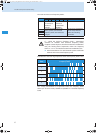
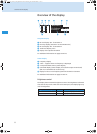
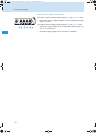
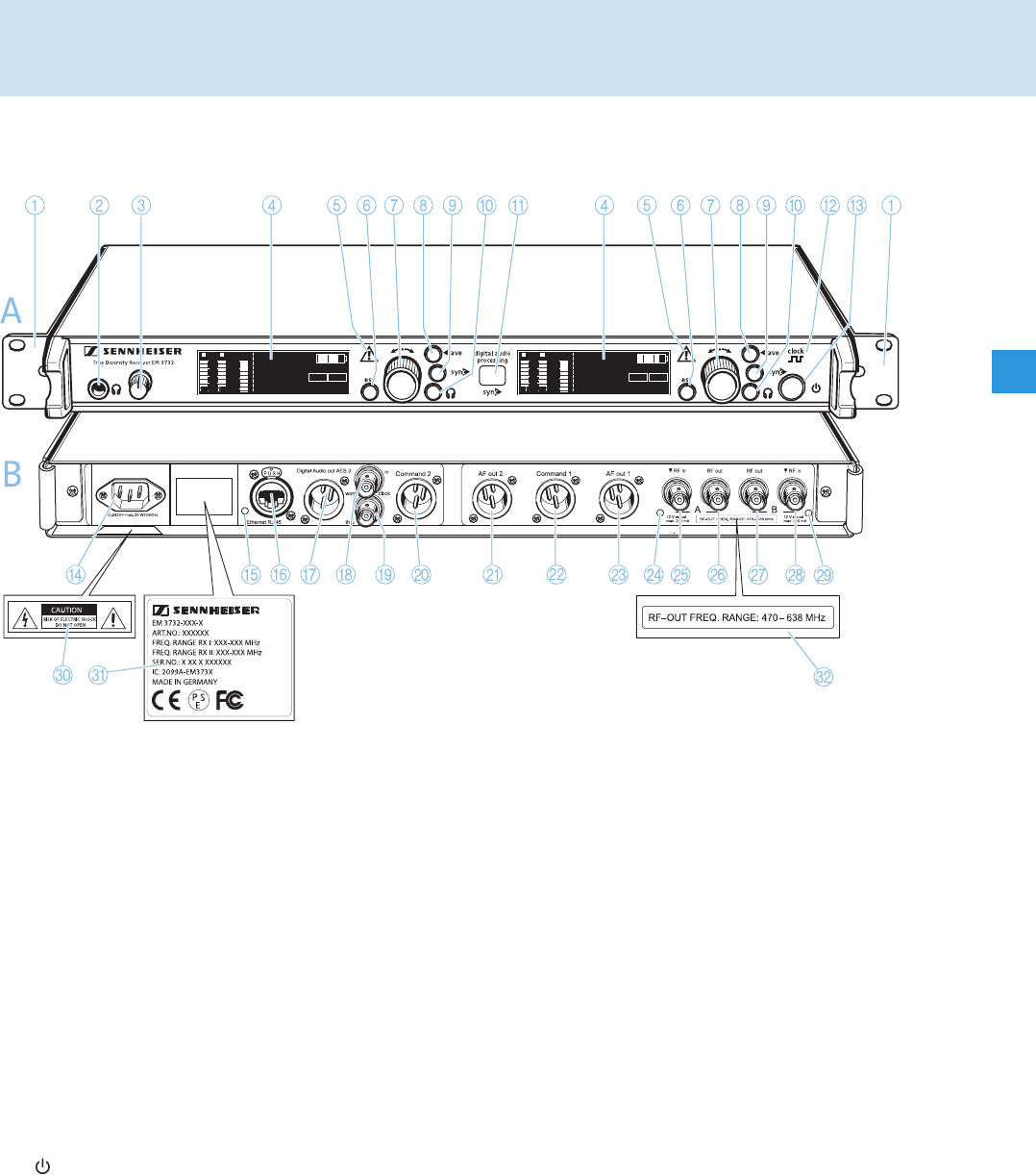
*) The audio outputs marked with the number “1” output the audio signal of the left receiver of the twin
receiver (as viewed from the front); the audio outputs marked with the number “2” output the audio signal of
the right receiver.
300
100
30
10
10
50
100
PEAK
μV
RF
% DEV
M
H
z
790.800
03.03
BANK
CH
A B
COM
AF
300
100
30
10
10
50
100
PEAK
μV
RF
% DEV
M
H
z
790.800
03.03
BANK
CH
A B
COM
AF
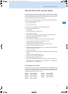
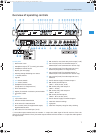
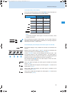
A Front panel
1 Rack mount “ears”
2 Headphone output, ¼“ (6.3 mm) jack socket
3 Headphone volume control
4 Display (see next page)
5 Warning triangle indicating error states
6 esc button, backlit
7 Jog dial
8 save button, backlit
9 sync button, backlit
0 Headphone button, backlit
(except EM 3731 single receiver)
A Infra-red interface
B Display for external word clock synchronization
C button, backlit
B Rear panel
D 3-pin mains socket
E LED for LAN data transmission
F RJ 45 socket for LAN connection
G XLR-3 socket (male) for digital audio output,
digital balanced, AES3
H BNC socket for word clock input (75 Ω)
I BNC socket for word clock daisy chain output (75 Ω)
J XLR-3 socket (male) for Command output 2*,
balanced (EM 3732 Command twin receiver only)
K XLR-3 socket (male) for audio output AF out 2*,
balanced (except EM 3731 single receiver)
L XLR-3 socket (male) for Command output 1*,
balanced (EM 3732 Command twin receiver only)
M XLR-3 socket (male) for audio output AF out 1*,
balanced
N LED for booster supply of antenna input A
O BNC socket, antenna input A
(ANT A – RF in, DC OUT, 50 Ω)
P BNC socket, daisy chain output A
(ANT A – RF out)
Q BNC socket, daisy chain output B
(ANT B – RF out)
R BNC socket, antenna input B
(ANT B – RF in, DC OUT, 50 Ω)
S LED for booster supply of antenna input B
T Label with hazard warnings
U Type plate
V Label with frequency range for daisy chaining
EM3732_516551_0108_Sp6.book Seite 7 Dienstag, 18. Dezember 2007 11:55 11