


Other connections
10
65
En
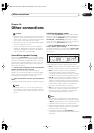
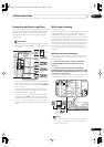
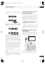
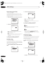
When setting up an i.LINK network, it’s important that
the components form an open ended chain (fig. 1), or a
tree (fig. 2).
The system will not work if the connected components
form a loop. If a loop is detected, the message
LOOP
CONNECT
shows in the display. Figs. 3 and 4 show
connections that form a loop.
Another consideration when connecting i.LINK devices
is the speed of the interface. At present there are three
speeds; S100 (slowest), S200 and S400 (fastest). This
receiver uses the S400 type. Although you can use
components with different speeds together, we
recommend connecting slower-speed components at
the edge of the network if possible (shown by the shaded
boxes in figs. 1 and 2). This will keep the network free of
bottlenecks.
When used within an i.LINK network, this receiver must
be on for the i.LINK connection to be maintained. Other
components in the network may or may not maintain the
connection in standby (none will when the power is
completely off)—check the operating instructions
supplied with individual components. Note that the audio
may be momentarily interrupted if a component in the
i.LINK network is switched on/off, or its i.LINK
connection is switched on/off.
This product complies with the following i.LINK interface
specifications:
1) IEEE Std. 1394a-2000, Standard for a High Performance
Serial Bus
2) Audio and Music Data Transmission Protocol 2.0
Following the standard for AM824 sequence adaptation
layers, the product is compatible with IEC60958 bitstream,
DVD-A and SACD.
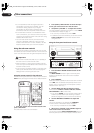
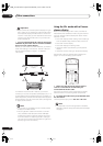
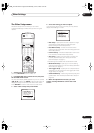
Switching components on and off
using the 12 volt trigger
VSX-2014i model only
You can connect components in your system (such as a
screen or projector) to this receiver so that they switch on
or off using a 12 volt trigger when you select an input
function. However, you must specify which input
functions switch on the trigger using the System Setup
menu (see
12 Volt Trigger Setup
on page 72 to do this).
Note that this will only work with components that have a
standby mode.
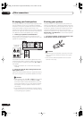
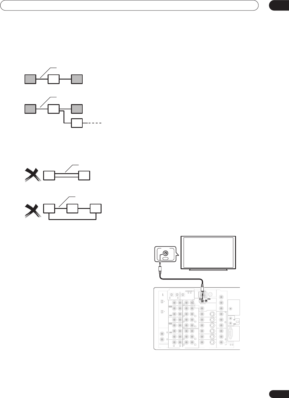
• Connect the 12V TRIGGER jack of this receiver to
the 12V TRIGGER of another component.
Use a cable with a mono mini-plug on each end for the
connection.
• The trigger maximum power is DC OUT 12V/100mA.
After you’ve specified the input functions that will switch
on the trigger, you’ll be able to switch the component on
or off just by pressing the input function(s) you’ve set on
page 72.
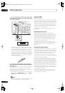
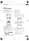
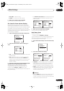
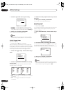
Using this receiver with a Pioneer
plasma display
If you have a Pioneer plasma display, you can use an
SR+ cable (see note below) to connect it to this unit and
take advantage of various convenient features, such as
automatic video input switching of the plasma display
when the input is changed.
Note that the illustration above shows the VSX-2014i
however, connection for the VSX-1014 is the same.
fig. 1
fig. 2
i.LINK cable
i.LINK cable
fig. 3
fig. 4
i.LINK cable
i.LINK cable
ASSIGNABLE
CD
IN
IN
IN
IN
IN
IN
OUT
OUT
CD-R/
TAPE/MD
VIDEO1
DVR /
VCR
DVD/
LD
TV/
SAT
OUT
PRE
OUT
CEN-
TER
CEN-
TER
SUR-
ROUND
SUR-
ROUND
SUR-
ROUND
BACK
(
Single
)
FRONT
FRONT
SUBW.
SUBW.
MULTI CH IN
CONTRO
L
OOM
&
SOURC
E
MONITOR
MONITOR
VIDEO1
DVR /
VCR
TV/
SAT
DVD/
LD
IN
IN
IN
VIDEO
COMPONENT
ASSIGNABLE
MULTI-
ROOM &
SOURCE
AUDIO
VIDEO S-VIDEO
RS - 232C
IN
IN
OUT
OUT
OUT
ANTENNA
AM
LOOP
FM
U
NBAL 7
5
Ω
M
O
NIT
O
R
OUT
12V
TRIGGER
Y
Y
P
B
P
R
P
B
P
R
Y
P
B
P
R
〜
1 2
2
IN
1
R
L
R L
R L
R
R
L
L
R
R
L
L
PLAY
PLAY
REC
REC
OUT
IR
IN
VIDEO
(
DC OUT12V/
100mA MAX
)
S400
S400
IN
(
DVD/
LD
)
IN
(
CD
)
DIGITAL
IN
(
CD-R/
TAPE/MD
)
IN OUT
DIGITA
L
(
TV/SAT
)
〜
4
3
2 1
1
4
OUT
CONTROL
Pioneer plasma
display
VSX_2014TX.book.fm Page 65 Wednesday, June 2, 2004 5:21 PM