


35
RQT9129
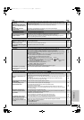
Optional connections and settings
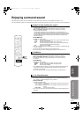
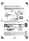
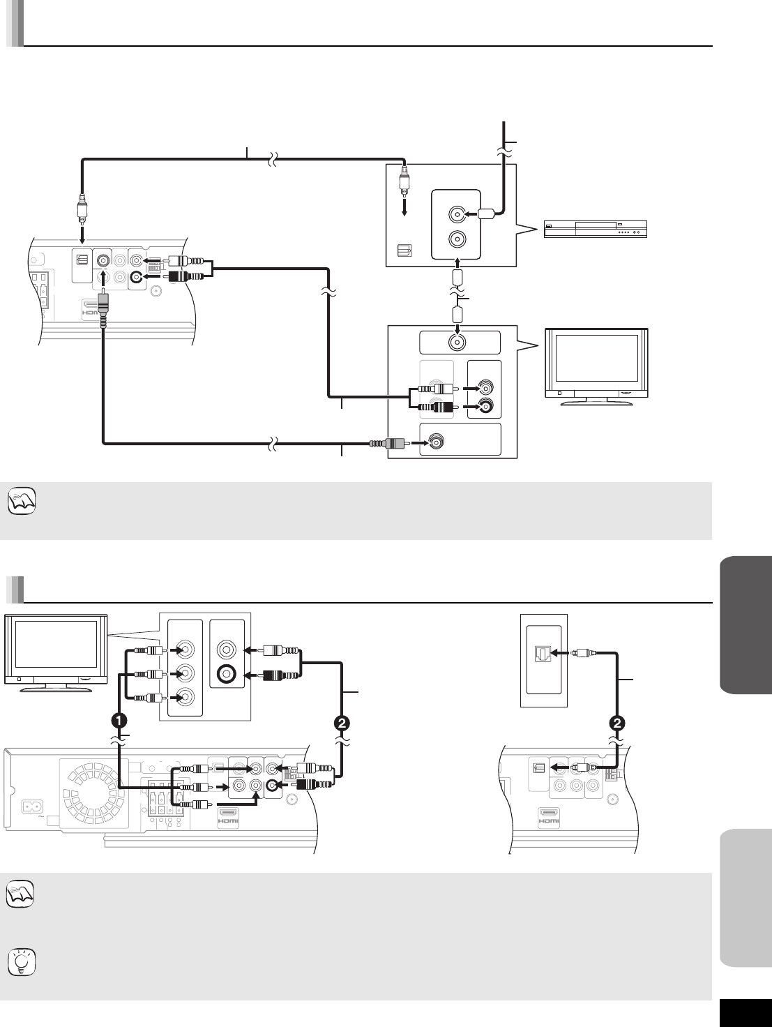
Use the following connections when you want to output audio of your cable TV or VCR through this unit’s speakers.
≥Do not connect through the video cassette recorder.
Due to copy guard protection, the picture may not be displayed properly.
≥Turn off all equipment before connection and read the appropriate operating instructions.
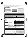
Connection to Set Top Box (Satellite receiver, Cable box, etc) or video cassette
recorder
This unit can decode the surround signal from the Set Top Box (Satellite receiver, Cable box, etc).
Press [N, O SELECT] several times to select
“
D-IN” (DIGITAL IN).
§
These audio connections will enable you to play audio from your television through your home theater system (> 17).
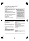
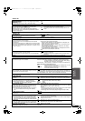
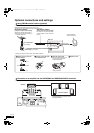
Connection to a TV with component video cable
≥Connect terminals of the same color.
≥Set “Black Level Control” to “Darker”. (> 32)
≥Some discs prohibit high definition video output from COMPONENT VIDEO OUT terminals. In this case, video resolution is converted
to 480p.
§
These audio connections will enable you to play audio from your television through your home theater system (> 17).
To enjoy high definition/progressive video
≥Connect to a TV that supports 480p or higher.
≥Set “Component Video Resolution” to “480p”, “720p” or “1080i”. (> 33)
≥Set “HDMI Video Mode” to “Off”. (> 33) Otherwise, the video is output as 480i.
OPTICAL
OUT
RF IN
RF OUT
AUDIO
OUT
VIDEO IN
AUDIO
IN
RF IN
L
R
L
R
OPTICAL IN
L
R
DIGITAL
COMPONENT
VIDEO OUT
VIDEO OUT
Y
AUXP
R
PB
SURROUND
AV OUT
AKERS
R
L
6
ǡ
ER
FRONT
2
1
FM ANT
ANT
EXT
LOOP
AM
75ǡ
GND
ANT
LOOP
TV
Video cable (included)
RF cable (not included)
Set Top Box (Satellite
receiver, Cable box, etc) or
video cassette recorder
(not included)
To your cable TV service or TV antenna
RF cable
(not included)
Optical digital audio cable
§
(not included)
Main unit
Audio cable
§
(not included)
NOTE
OPTICAL IN
L
R
DIGITAL
COMPONENT
VIDEO OUT
VIDEO OUT
Y
AUXP
R
PB
SURROUND
SURROUND
BACK
AV OUT
SPEAKERS
R
L
6
ǡ
6
ǡ
CENTER
6
ǡ
SUBWOOFER
FRONT
6
5
2
1
FM ANT
ANT
EXT
LOOP
AM
75ǡ
GND
ANT
LOOP
AC IN
OPTICAL IN
L
R
DIGITAL
COMPONENT
VIDEO OUT
VIDEO OUT
Y
AUXP
R
PB
AV OUT
L
FRONT
1
FM ANT
ANT
EXT
LOOP
AM
75ǡ
GND
ANT
LOOP
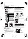
OPTICAL
OUT
L
R
AUDIO OUT
COMPONENT
VIDEO IN
Y
P
R
PB
Main unit
Component Video cable (not included)
TV
Audio cable
§
(not included)
≥The optical digital
audio cable can be
used when connecting
to televisions with
optical out terminals
(> right).
Optical
digital audio
cable
§
(not included)
NOTE
TIPS
Reference
Advanced
operations
SC-BT100P-ENG.book 35 ページ 2008年2月20日 水曜日 午後6時22分