


744T User Guide and Technical Information
6
firmware v. 1.04 Features and specifications are subject to change. Visit www.sounddevices.com for the latest documentation.
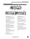
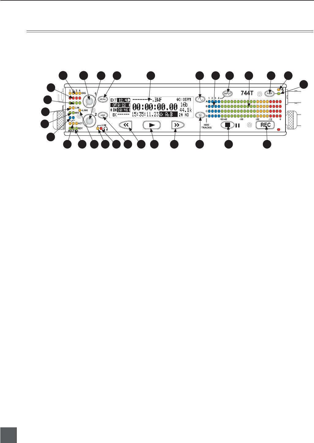
1) Digital Input LEDs
Indicates the presence of digital signal
on the respective input. When fl ashing,
indicates that digital input is selected
but no valid digital clock signal is pres-
ent.
2) Input 1 Gain
Controls the analog gain (input trim) of
the channel 1 input. Normal mic input
range is from 25 dB to 70 dB, low gain
mic range is from 10 dB to 55 dB, line
input range is from −6 dB to 18 dB. For
line-level inputs, this control can be
defeated and gain can be setup menu-
controlled. If the LCD display shows
“locked” when the pot is turned, gain
control of the line-level input is menu-
controlled. When inputs are linked as a
stereo pair input gain 1 controls the gain
of both inputs.
3) Input 2 Gain
Controls input 2, as in #2 above. When
inputs are linked as a stereo pair input
controls left-to-right balance.
4) MENU Key
Used to access all 744T setup menu
selections. When in menu mode, used to
move up through the menu selections.
Pressing the HDD and MENU keys
simultaneously brings up the time code
jam menu.
5) LCD Display
Primary display of 744T status. The
LCD is backlit using the LCD backlight
control (#15).
6) Tone Oscillator
Tone frequency, tone level, and routing
are controlled in the setup menu. Press
and hold to activate the tone oscillator.
7) Input-to-Track Matrix LEDs
Blue LEDs indicate inputs (1, 2, 3, 4)
enabled for recording to tracks (A, B, C,
D). A solid blue LED indicates an input
is routed to a track. A fl ashing LED dur-
ing “custom” routing mode shows the
selected input/track combination.
8) INPUT Select Key
Pressing this key cycles through the six
factory preset input-to-track routing
combinations plus the custom routing
menu. In the custom routing menu any
input can be routed to any track. See
Input-to-Track Routing, page 18.
9)
Level Meter LEDs
Four, 19-segment track level-meters in-
dicate level in dBFS. Metering ballistics
are selected in the setup menu.
10)
Power Key
Press and hold (150 ms) to power up the
744T. Press and hold (1 second) to power
down.
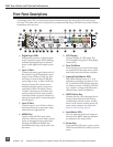
Front Panel Descriptions
All settings of the 744T can be accessed and monitored through the front panel LCD and naviga-
tion keys. This allows the unit to be placed in a production bag along with fi eld mixers and wireless
transmitters and receivers.
14 20 21 22 23 24
26
27
28
29
5 6
15 16 17 18 19
25
4
2 1
10
13
7 8 9 3
12
11