


Hardware Descriptions
11
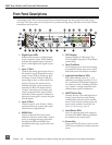
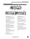
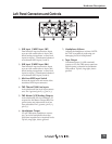
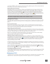
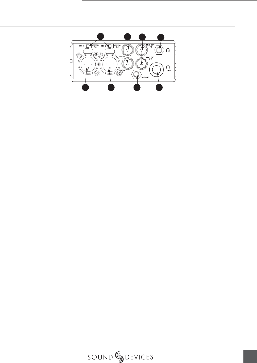
1) XLR Input 1/AES3 Input 1&2
Dual function input connection. Input
type set with switch above. Active-bal-
anced analog microphone- or line-level
input for input 1. Transformer-balanced
two-channel AES3 input (1 and 2).
2) XLR Input 2/AES3 Input 3&4
Dual function input connection. Input
type set with switch above. Active-bal-
anced analog microphone- or line-level
input for input 2. Transformer-balanced
two-channel AES3 input (3 and 4).
3) Mic-Line-AES3 Input Switch
Selects the input level and mode of the
associated XLR input connector.
4) TA3 Channel 3&4 Line Inputs
Active-balanced line-level input connec-
tors. Pin-1 ground, pin-2 (+), pin-3 (−).
5)
TA3 Master (L/R) Analog Outputs
Active-balanced, line-level analog L/R
outputs for the Master Output Bus. Pro-
gram source and attenuation level are
user selectable. Pin-1 ground, pin-2 (+),
pin-3 (–).
6)
Headphone Output
3.5 mm TRS stereo headphone connec-
tor. Can drive headphones from 8 to
1000 ohm impedances to required levels.
Tip left, ring right, sleeve ground.
7) Headphone Volume
Adjusts the headphone volume. NOTE:
the 744T is capable of producing ear-
damaging levels in headphones.
8) Tape Output
Unbalanced tape (–10 dBv nominal)
output on 3.5 mm TRS stereo connector.
Signal source is identical to the Master
Output Bus. Tip left, ring right, sleeve
ground.
Left Panel Connectors and Controls
1 8 7
6
5
4
2
3