


Input Setup and Control
15
pressing the HDD key. If the inputs are in line level mode, phantom power will not activate from the
shortcut keys and must be activated from the menus.
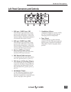
Input Limiters (mic-level only)
Microphone inputs 1 and 2 each have a limiter circuit designed to prevent input overload. In nor-
mal operation, with proper gain settings, the limiters should rarely engage. When activated, these
limiters will prevent unusually high input signal levels from clipping the analog input stage of
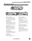
the preamp. The front panel LIM LED ( ) shows that the limiter is engaged. Limiter activity is
indicated by additional front panel LEDs, one for each input channel ( ). The input limiters are
active only with mic-level inputs. The limiters are engaged by (factory) default.
When limiters are engaged, audio on channels 1 and 2 is limited to −6 dBFS.
Microphone-Level Control
Microphone gain is controlled by the front panel recessed knobs. The gain control adjusts an analog
gain stage and is identical to the input trim on a mixing console or stand-alone microphone pream-
plifi er.
Line-Level Gain Control
When in line-level position, the gain for inputs 1 and 2 is controlled by the front panel recessed
knobs or by a menu sensitivity setting. When set for front panel control, the user menu selection for
input 1 and 2 line input sensitivity are lined out and not accessible.
Input Linking (mic- and line-level)
Analog inputs 1 and 2 can be linked as a stereo pair. When linked, the channel 1 front panel potenti-
ometer controls the signal level of both inputs, and the channel 2 pot controls the left-to-right balance
of the pair. When the inputs are linked, their peak limiters are linked, as well.
When set as an MS pair, the inputs gain and balance for the pair work the same as stereo linking.
There is no stereo width control as an MS pair since gain is adjusted.
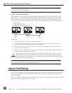
High-Pass Filters (microphone-level only)
The high pass fi lters on the microphone inputs use a combination of analog and digital fi lters to re-
duce sensitivity to low frequency signals. When the high-pass is engaged on an input, its front-panel
LED illuminates to indicate it is active ( ). The fi rst pole of the high-pass circuit is an analog fi lter
at 40 Hz, 6 dB per octave and is part of the microphone preamplifi er circuit. Additional poles of
high-pass fi ltering are done in DSP.
Several frequency and slope combinations are selectable, including corner frequencies of 40, 80, 160,
or 240 Hz, and fi lter slopes of 12 dB, 18 dB, or 24 dB per octave. The high-pass is selected in the setup
menu for each input independently.
Shortcut: The fi lters can be toggled with a two-key combination. Press and hold the LCD back-
light key and press the menu key for channel 1 high-pass. Press and hold the LCD backlight
key and press the HDD key to toggle channel 2 high-pass.
Gain Range (microphone-level only)
The microphone inputs operate in two gain ranges, normal and low. The normal range is from 25 dB
to 70 dB of gain. The low range is from 10 dB to 55 dB. The low range is useful for high SPL record-
ing environments.
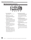
Analog Inputs 3 & 4
Appearing on TA3 connectors, inputs 3 and 4 accept balanced or unbalanced line-level signals. These
inputs have few controls and are typically fed from the output of a mixer or preamplifi er.