


Setup Menu
45
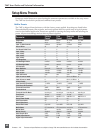
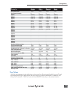
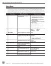
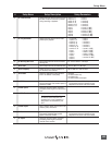
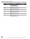
# Setup Name Setup Description Setup Parameters
11
Rec: Timer Stop
Set a specific time/date to stop record-
ing. May be used with or without the Rec:
Timer Start. May be set before the Timer
Start time to temporarily stop recording
and then resume recording with Timer
Start.
<enter time, date>
12
Rec: Error Handler
Sets the behavior when a hard drive
write error occurs.
• Stop recording
• Create New Take
13 Input: Routing Allows the user to setup their routing
matrix among all available inputs and
tracks. There are four preset routings and
one custom routing available. Pressing
the input select key repeatedly will cycle
through all preset routings.
Primarily accessible from the Input
Select Key.
• 1 A / 2 B
• 1 A / 1 B
• 1 A,B / 2 A,B
• 1 A / 2 B / 3 C / 4 D
• 1,2,3 A / 1 B / 2 C / 3 D
• 1 A,C / 2 B,D
• 3 C / 4 D
• Custom Route
14
15
Input 1: 48V Phantom
Input 2: 48V Phantom
Enables or disables 48 V phantom power
on inputs 1 and 2.
• Off
• On - Mic
• On - Mic and Line
16
Mic Inputs: Limiter
Enables or disables the analog input
limiter on input 1 and 2 mic preamps.
• Disabled
• Enabled
17
18
Mic Input 1: Low Cut
Mic Input 2: Low Cut
Enables the high-pass (low cut) filter to
reduce sensitivity to low frequencies.
• Disabled
• Enabled
19
20
Mic Input 1: Low Cut Freq
Mic Input 2: Low Cut Freq
Selection of twelve high-pass filter
frequency and slope combinations for
microphone inputs.
• 40, • 80, • 160, • 240 Hz @ 12 dB/oct
• 40, • 80, • 160, • 240 Hz @ 18 dB/oct
• 40, • 80, • 160, • 240 Hz @ 24 dB/oct
21
22
Mic Input 1: Gain Range
Mic Input 2: Gain Range
Selects the sensitivity of the microphone
input. Low sensitivity is used for very
loud and/or very hot microphones.
• Normal
• Low
23
24
Input 1, 2: Source
Input 3, 4: Source
Forces the inputs to analog or digital
mode. Default is auto-select.
• Auto-select
• Analog
• Digital (S/PDIF/AES)
• Disabled (Power Save)
25
Input 1,2: Linking, MS
Selects whether the input 1 & 2 levels are
controlled independently or grouped as a
pair with or without mid-side decoding.
• Unlinked
Inputs 1 and 2 operate independently
• Linked 1/2
Inputs are linked, channel 1 pot controls
level, channel 2 pot controls pan
• Linked 1/2 and MS
Inputs are linked, channel. 1 pot controls
level, channel. 2 pot controls pan and are
decoded for MS stereo.
26
Line Input 1,2: Gain Control
When inputs 1 and 2 are in LINE input
mode, selects whether the gain setting is
controlled by the front panel knobs or by
the menu sensitivity settings below.
• Use front panel knobs
• Use sensitivity settings
27
28
29
30
Line Input 1: Gain
Line Input 2: Gain
Line Input 3: Gain
LIne Input 4: Gain
Adjusts the input sensitivity in 0.1 dB
steps -6 dB and +18 dB.
Meters show a pre-fader level of the input sig-
nal of all four inputs on their respective meters
to aid in the adjustment.
31
32
33
34
Input 1: Delay
Input 2: Delay
Input 3: Delay
Input 4: Delay
Sets a digital delay for each input. Can
be used to compensate for delay in vari-
ous digital wireless microphone units or
digital processors.
0 µsec to 30,000 µsec up to 48.048 kHz Fs
0 µsec to 15,000 µsec up to 96.096 kHz Fs
0 µsec to 7,500 µsec up to 192 kHz Fs