


744T User Guide and Technical Information
12
firmware v. 1.04 Features and specifications are subject to change. Visit www.sounddevices.com for the latest documentation.
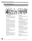
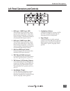
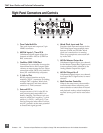
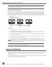
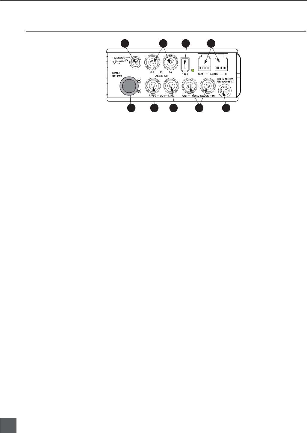
1) Time Code Multi-Pin
Time code input and output on 5-pin
LEMO
®
connector.
2) AES3id Inputs 1/2 and 3/4
Unbalanced digital inputs accept four
channels of either AES3 or S/PDIF on
BNC connectors.
3) FireWire (IEEE-1394) Port
Connection to a computer for access the
internal hard drive and Compact Flash
volumes as mass storage devices. Direct
connection to Mac OS (X-only) and Win-
dows (XP- and 2000-only) computers.
4) C. Link In/Out
RS-232 protocol interface on 6-pin
modular (“RJ-12”) connector for linking
multiple 744T’s together. Word clock,
machine transport, and time code are
carried on C. Link connector.
5)
External DC In
Accepts sources of 10–18 volts DC for
unit powering and removable Li-on
battery charging. The Hirose 4-pin con-
nector is wired pin-1 negative (−), pin-4
positive (+). Pin-2 (−) and pin-3 (+) are
used to charge the removable Li-on bat-
tery. DC ground is at the same potential
as chassis and signal ground.
6)
Word Clock Input and Out
Provides clock input and output for the
744T. Word input accepts sample rates
between 32 kHz and 192 kHz. Word
clock out is rate that box is running.
There is no sample rate conversion util-
ity in the 744T.
7) AES3id Master Output Bus
Unbalanced digital output, two-channel,
for the Master Output Bus. Signal source
is menu-selected and is identical to the
Analog Master Output Bus signal.
8) AES3id Output Bus 2
Unbalanced digital output, two-channel,
for Output Bus 2. Signal source is menu-
selected.
9) Multi-Function Controller
When in the setup menu, the controller
scrolls between menu selections; push
enters selection or enters data. In record
and playback modes, selects headphone
monitor source; pus-h action user select-
able.
Right Panel Connectors and Controls
1
9 8 7 6 5
4 3 2