744T User Guide and Technical Information
20
firmware v. 1.04 Features and specifications are subject to change. Visit www.sounddevices.com for the latest documentation.
Outputs – Analog and Digital
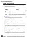
The 744T has two discrete output buses , the Master Output Bus and Output Bus 2. Each of these
two-channel buses are assigned their audio sources independently, enabling the 744T to feed mul-
tiple sources with unique two-channel program.
The chart below shows the audio sources available for the Master Output Bus and for Output Bus 2.
The audio sources for each output bus are selected in the setup menu.
Master Output
Bus and Output
Bus 2 Sources
Description
Inputs 1,2
Inputs 3,4
Stereo input pairs. Input 1 (and 3) is assigned to left output; input 2 (and 4) is assigned to right
output.
When inputs are selected as the source for the outputs, the state of recording or playback
activity has no effect on the output signal. This allow uninterrupted audio at the outputs.
Tr ack s A,B
Tr ack s C,D
Stereo track pairs. Track 1 (and 3) are assigned to the left output; track 2 (and 4) is assigned to
right output. On playback, will play as track monitor.
Monitor A,B
Monitor C,D
Stereo monitoring of playback (post-record) track pairs. Highlighted media is source of monitor
program. Track 1 (and 3) is assigned to left output; track 2 (and 4) is assigned to right output. When
not playing or recording there is no output. There is significant delay in the monitor signal while
recording due to the record buffer topology.
Master Output Bus
Audio signals routed to the Master Output Bus are sent to three output connections:
• analog line out, 2 x TA3, two-channel
• analog tape out, 3.5 mm TRS, two-channel
• digital 1, AES3id, BNC connection, two-channel
Analog Line Out L, R
The analog line outputs are active-balanced line-level signals on Switchcraft TA3M locking connec-
tors. The output level is a nominally +4 dBu at −20 dBFS. The level of the line output can be attenu-
ated in the setup menu by up to 40 dB in 1 dB increments.
Analog Tape Output
The tape output connection is stereo, unbalanced consumer output level (–10 dBV) on a TRS 3.5 mm
connector. Output attenuation does not affect this output level.
Digital AES3id Output
The unbalanced AES3id output is directly compatible with most S/PDIF inputs. Attenuation to the
Master Output Bus affects both analog and digital signals.
Output Bus 2
Just as with the Master Output Bus, Output Bus 2 can be assigned signal sources from inputs or
tracks. Sources assigned to Output Bus 2 are exclusive and do not affect the assignments to the Mas-
ter Output Bus or headphone assignments. The same signal sources available for the Master Output
Bus are available for Output Bus 2 (see chart above).
Digital AES3id Output 2
Output Bus 2 appears solely on the AES3id BNC output connector. There is no analog output con-
nections for Output Bus 2. The unbalanced AES3id output is directly compatible with most S/PDIF
inputs. The maximum output level is 0 dBFS and can be attenuated in the setup menu in 1 dB incre-
ments by 40 dB.


