


85
Zone 2
—Continued
Using the 12V Trigger
While Zone 2 is active on the TX-NR901, the ZONE 2
12V TRIGGER OUT outputs 12 volts (100 milliamperes
max). By connecting this to the 12-volt trigger input on,
say, a power amp in Zone 2, the power amp will turn on
and off automatically when Zone 2 is turned on and off
on the TX-NR901.
To use the remote controller to control the TX-NR901
from Zone 2, you’ll need one of the following commer-
cially available multiroom remote control kits:
• Onkyo Multiroom Kit (IR remote controller extension
system)
• Multiroom AV distribution and control systems such
as those made by Niles and Xantech.
These kits can also be used when the TX-NR901 is not
in line of sight of the remote controller, for example,
when it’s installed inside a cabinet.
If you have the RC-549M remote controller (supplied
with American and Australian models), you can set the
transmission signal format to RF for use with the
optional RF Receiver (see page 98).
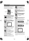
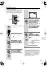
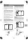
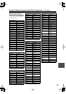
Using a Multiroom Kit with Zone 2
In the following diagram, an IR receiver picks up the
infrared signals from the remote controller in Zone 2 and
feeds them to the TX-NR901 in the main room via the
connecting block.
• On the Remote Setup menu, set the Position setting to
“Zone 2” (see page 48).
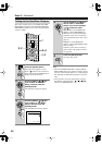
Connect the miniplug cable from the connecting block to
the TX-NR901’s IR IN socket as shown below.
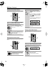
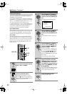
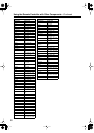
Using a Multiroom Kit with a Cabinet
In the following diagram, an IR receiver picks up the
infrared signals from the remote controller and feeds
them to the TX-NR901 in the cabinet via the connecting
block.
• On the Remote Setup menu, set the Position setting to
“Main” (see page 48).
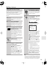
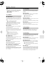
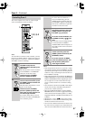
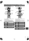
Using a Multiroom Kit with Other
Components
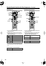
In the following diagram, an IR emitter is connected to
the TX-NR901’s IR OUT socket and placed in front of
the other component’s remote control sensor. Only infra-
red signals received at the IR IN socket are fed to the
other component. Signals picked up by the TX-NR901’s
remote control sensor are not passed on.
Connect the IR emitter to the TX-NR901’s IR OUT
socket as shown below.
Using the Remote Control in Zone 2
TX-NR901
Connecting
block
Remote controller
IR Receiver
Main room Zone 2
Signal flow
TX-NR901
I
R
IN
OUT
from the connecting block
Miniplug cable
IR IN
TX-NR901
Connecting
block
Remote controller
IR Receiver
Inside
cabinet
Signal flow
TX-NR901
IR IN
IR OUT
Connecting
block
IR Receiver
Remote controller
Signal flow
IR Emitter
Other component
TX-NR901
I
R
IN
OUT
Remote control
sensor
Other component
Emitter
IR Emitter
Signal flow
Miniplug
Miniplug cable