


38 SMART ANTENNA User Manual Rev 6
Appendix A Technical Specifications
A.3 Connector Pin Assignments
A.3.1 RS-232
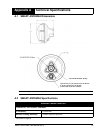
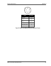
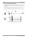
Pin numbers and signals for the 7-pin power/communication connector are shown below. There is also a 6-pin
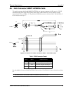
RS-232 version of the SMART ANTENNA, see Figure 20 on Page 39. The orientation of these connectors on
the SMART ANTENNA can be seen in Figure 6 on Page 15. The most popular model (part number SA-232-
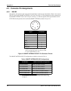
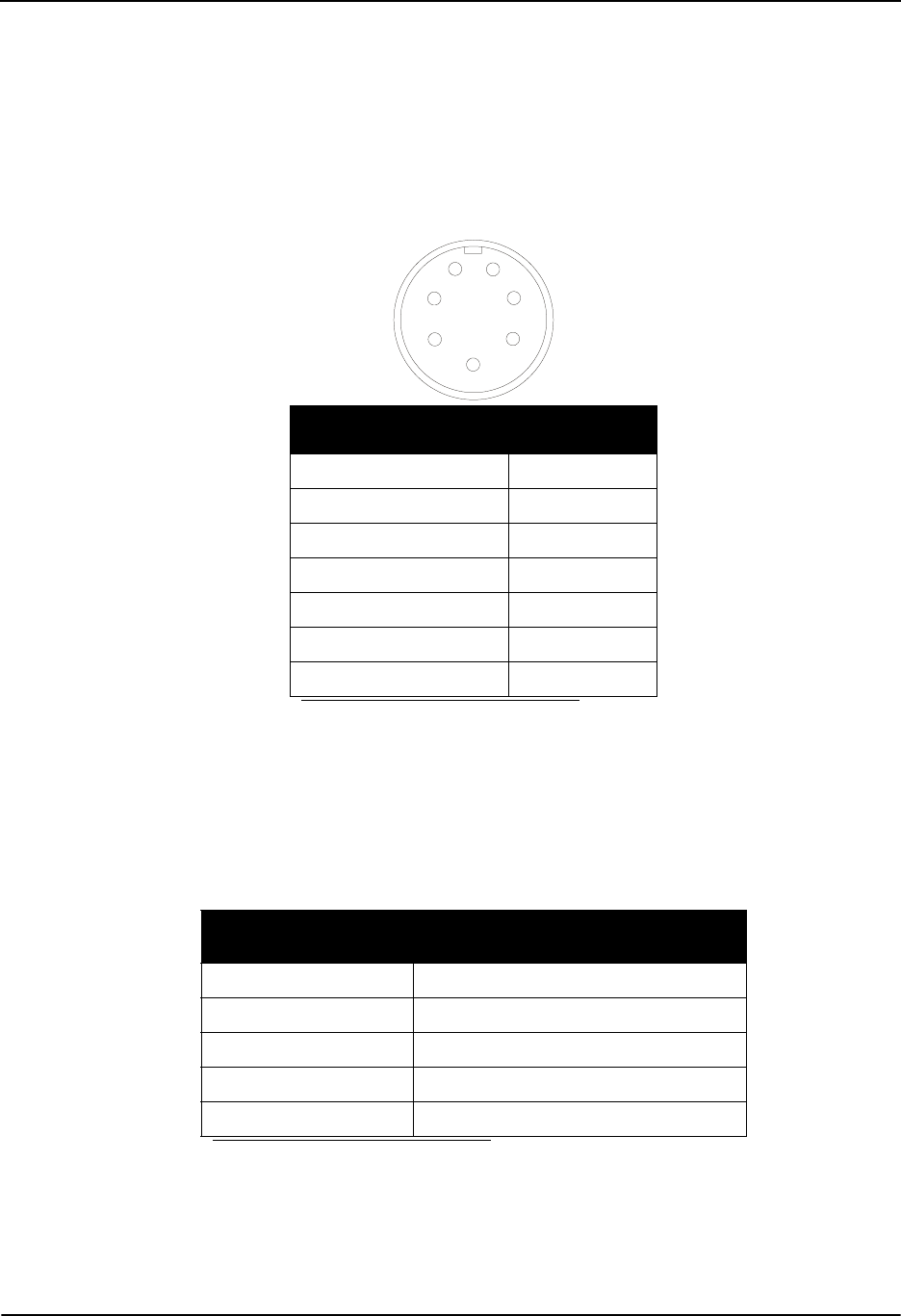
07W-XXX) has the pinouts (from outside the SMART ANTENNA) shown in Figure 19:
Figure 19: SMART ANTENNA RS-232 7-Pin Connector Pinouts
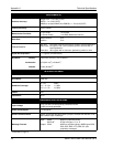
The SMART ANTENNA RS-232 configurations available are shown in Table 4:
Table 4: SMART ANTENNA RS-232 Configurations
Signal Pin Number
VOLTAGE_INPUT (Vin) 7
GROUND 6
RX_2 2
1PPS
a
a. A buffer circuit operates from Vin (9 to 36 VDC).
That is, the signal goes from Vin, down to 0 VDC
for 1 ms, and then back up to Vin
.
5
TX_1 3
RX_1 1
GROUND 4
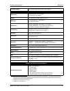
Part Number
a
a. The XXX in part numbers refers to software models. Please refer to
the SUPERSTAR II Firmware Reference Manual, see Reference [6]
on Page 12.
SMART ANTENNA Configuration
SA-232-07W-XXX White, 7-pin plastic connector
SA-232-06W-XXX White, 6-pin metal connector
SA-232-06G-XXX Green, 6-pin metal connector
DK-SA-232-07W-XXX Dev kit, white, 7-pin plastic connector
DK-SA-232-06G-XXX Dev kit, green, 6-pin metal connector
1
6
5
4
3
2
7