


8 - 15
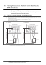
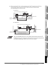
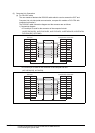
8.3 Wiring Precautions the Part which Matches the EMC Directives
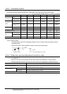
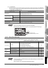
8.3.2 Grounding the ground cable
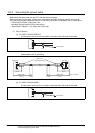
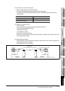
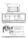
(3) Computer Link Connection
(a) For RS-232C cable
The user needs to fabricate the RS-232C cable which is used to connect the GOT and
Computer link unit side (serial communication, computer link module or PLC CPU with
computer link function).
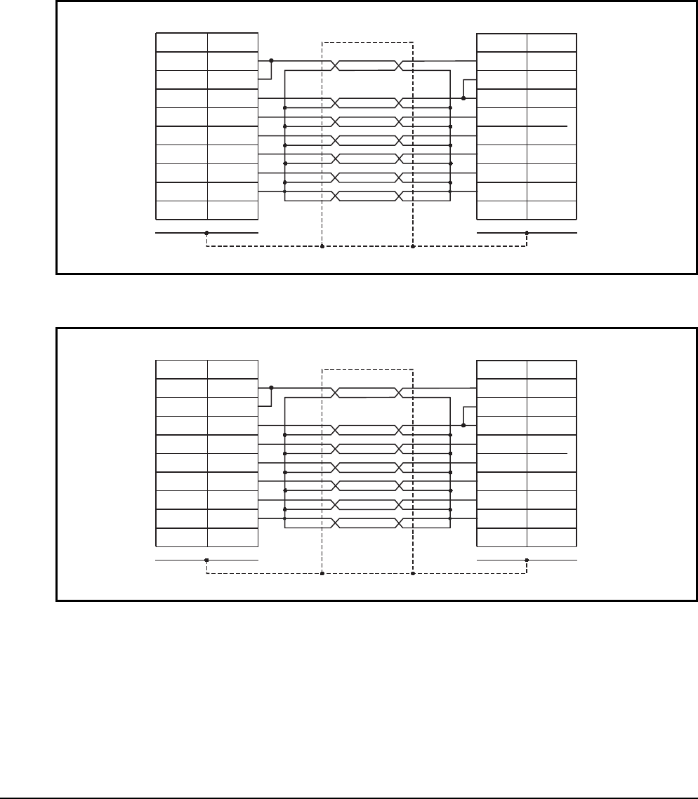
The RS-232C cable connection diagram and the connector are as follows.
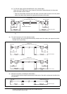
1) Connection diagram
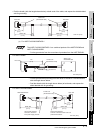
• If D-sub 9-pin is used for the connector of the computer link unit.
(A1SJ71QC24(-R2), A1SJ71UC24-R2, A1SJ71C24-R2, A1SCPUC24-R2, A2CCPUC24,
QJ71C24(-R2), QJ71CMO)
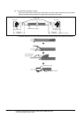
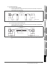
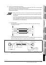
• If D-sub 25-pin is used for the connector of the computer link unit.
(AJ71QC24(-R2), AJ71UC24)
CS(CTS)
RS(RTS)
CD
RD(RXD)
SD(TXD)
DTR(ER)
DSR(DR)
SG
-
8
7
1
2
3
4
6
5
9
CD
RS(RTS)
CS(CTS)
SD(TXD)
RD(RXD)
DSR(DR)
DTR(ER)
SG
-
1
7
8
3
2
6
4
5
9
GOT side Computer link module side
Pin No.
Signal
Pin No.
Signal
Shell
Braided shield
Shell
CS(CTS)
RS(RTS)
CD
RD(RXD)
SD(TXD)
DTR(ER)
DSR(DR)
SG
-
8
7
1
2
3
4
6
5
9
CD
RS(RTS)
CS(CTS)
SD(TXD)
RD(RXD)
DSR(DR)
DTR(ER)
SG
-
1
7
8
3
2
6
4
5
9
GOT side Computer link module side
Pin No.
Signal
Pin No.
Signal
Shell
Braided shield
Shell