


8.3 Wiring Precautions the Part which Matches the EMC Directives
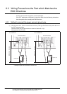
8.3.2 Grounding the ground cable
8 - 12
1
OVERVIEW
2
SYSTEM
CONFIGURATION
3
PERFORMANCE
4
NAMES OF
THE PARTS AND
THEIR SETTINGS
5
ROUGH
PRE-OPERATION
PROCEDURE
6
HANDLING
7
MAINTENANCE AND
INSPECTION
8
EMC DIRECTIVE
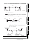
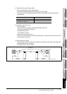
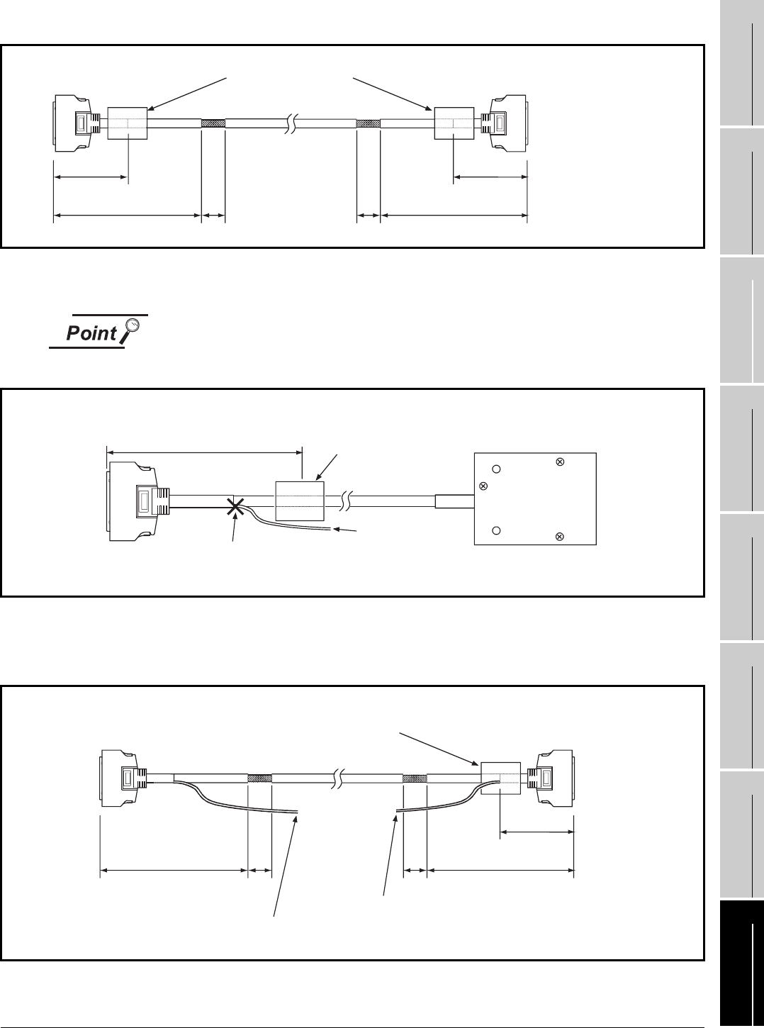
• Peel the sheath (with the length shown below) at both ends of the cable, and expose the shield braided
wire for grounding..
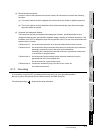
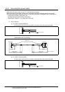
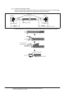
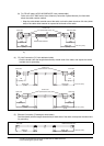
(c) For A8GT-C100/200/300EXSS-1
The A8GT-C100/200/300EXSS-1 is a combined product of the A8GT-EXCNB and
A8GT-C100/200/300BS.
• Cut the ground wire from the core where it protrudes from the A8GT-EXCNB..
• Cut the ground wires protruding from both ends of the A8GT-C100/200/300BS
with the length shown below.
• Peel the sheath (with the length shown below) at both ends, and expose the
shield braided wire for grounding..
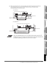
For A8GT-EXCNB
For A8GT-C100/200/300BS
130
130
GOT side
GOT side
Within 360
40 40
Ferrite core
(ZCAT3035-1330)
Unit: mm (inch)
Within 360
(5.12)
(1.57)
(14.17)
(5.12)
(14.17)
(1.57)
130
PLC side
Ferrite core
(ZCAT3035-1330)
Unit: mm (inch)
Ground wire
Cut
A8GT-C100
/200/300BS side
(5.12)
130
A
8GT-EXCNB side
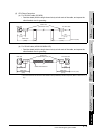
GOT side
Within 360
Within 360
40
40
Ferrite core
(ZCAT3035-1330)
Unit: mm (inch)
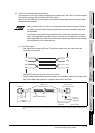
Ground wire (450mm)
Connect to FG of the
PLC power supply module
Ground wire (280mm)
Connect to FG of the GOT main unit
power terminal block
(1.57)
(14.17)
(5.12)
(1.57)
(14.17)